Some quotes on tools, relevant to software engineering
- Software development is like war:
- "We shall not fail or falter; we shall not weaken or tire.
Neither the sudden shock of battle nor the longdrawn trials
of vigilance and exertion will wear us down. Give us the
tools and we will finish the job." -- Sir Winston Churchhill
- Do you only need one or two tools?
- "An apprentice carpenter may want only a hammer and saw, but a master craftsman employs many precision tools. Computer programming likewise requires sophisticated tools to cope with the complexity of real applications, and only practice with these tools will build skill in their use." -- Robert Kruse
- Do you only need one or two tools?
Why is Software Engineering Crucial?
Because the larger a program gets, and the more features you add, the more bugs you get. Why? Because things get too complex for us to handle. Until we can solve this unsolvable puzzle, Moore's Law is limited or revoked by our inability to utilize hardware, just as we are unable to utilize our own brain (wetware).
Belady-Lehman observed:
[D. Berry, The Inevitable Pain of Software Development,
Monterey Workshop 2002]
So, Software Engineering is All About Pain
Software Engineering, it turns out, is mainly about pain. Dan Berry, one of software engineering's luminary founding fathers, had this to say about software engineering methods:Each method, if followed religiously, works. Each method provides the programmer a way to manage complexity and change so as to delay and moderate the B-L upswing. However, each method has a catch, a fatal flaw, at least one step that is a real pain to do, that people put off. People put off this painful step in their haste to get the software done and shipped out or to do more interesting things, like write more new code. Consequently, the software tends to decay no matter what. The B-L upswing is inevitable.Dr. Berry goes on to give the following examples:
| Software Method | Pain |
|---|---|
| Build-and-fix | doesn't scale up |
| Waterfall Model | it is impossible to fully understand and document complex software up front |
| Structured Programming | Change is a nightmare: patch or redesign from scratch |
| Requirements Engineering | Haggling over requirements is a royal pain. |
| Extreme Programming | Writing adequate test cases is a pain |
| Rapid Prototyping | We can't bear to throw away the prototype! |
| Formal Methods | Writing formal specification, and verifying it, may be a pain. Changing requirements is definitely a pain. |
| Code inspections | Documentation prep for inspection is a pain; nobody wants to be inspected. |
| "Daily Builds" | Testing, regression testing, and possibly reworking your latest change to not break someone else's latest change is a pain. |
Introduction to UML
Read Textbook Chapter 2 if you have not already.UML stands for Unified Modeling Language. A "modeling language" is not a programming language, although some efforts have been made to "compile" UML diagrams down into code. UML was created when 3 very successful software engineering diagramming gurus banded together to wipe out the other 12 software engineering gurus. Actually, there was a serious need to create a common notation; prior to that, software engineers that worked with one guru's diagrams might not easily be able to read or understand software designs drawn by another software engineer who had been trained using another guru's diagrams.
Chapter 2 of Bruegge gives an overview of UML, featuring 5 common kinds of diagrams, starting with use case diagrams, which are the type we will study first.
- use case diagrams
- document how human users and other "external entities" perform tasks using the software system that is to be built.
- class diagrams
- document major application domain entities whose representation in the system will include state and behavior. These diagrams document the associations, or relationships, between classes. At implementation time, there may be many implementation classes in addition to whatever classes are written to correspond to domain classes and domain class relationships.
- interaction diagrams
- depict dynamic behavior and communication between objects. Generally more detailed elaborations and special cases of the "relationships" from class diagrams.
- statecharts
- These are finite automata, with software engineering semantics added. There are states, events, and behavior that goes on during states or events.
- activity diagrams
- flowcharts and similar diagrams in which the elements depicted represent the execution of a sequence of instructions.
Here's the CS Lab FAQ
Check it out; it provides some useful information on our current labs.Team Assignments
Nutter: JavaFischer: C++, Naresh Vinukonda: C++
"That was Easy..."
Extended discussion of hw #2 and class project.
SVN and Version Control
SVN stands for "Subversion", which is really just a cutesy name for this excellent revision control system. SVN is almost an improved clone of a popular system called CVS, and much of this discussion could apply to both of those systems interchangeably, but SVN is a little newer and better. It is a software version control system, whose primary function is to aid in the coordination of programmers on large projects. Compared with earlier tools SCCS (source code control system) and RCS (revision control system), SVN offers some significant advantages:- It allows all programmers to edit any file at any time. Earlier tools used a "locking" system to allow only one programmer to edit a file at a time.
- It semi-automatically merges changes by multiple programmers; if the edits do not conflict it is fully automatic, and if the edits are to the same place in the program, it notes the conflict, shows both versions, and requires the programmer(s) to resolve the conflicts manually.
- SVN works on multiple platforms (e.g. UNIX and Windows) and since it is open source, everyone can use it. Previous systems were not very portable (RCS) or proprietary and commercial (SCCS, PVCS, etc).
- SVN works over the internet, making it awesome for coordinating the development of public open source projects with personnel scattered around the world.
Major SVN Commands
SVN works using a "repository" which is a database for source files.Unless you are creating your own repository, the first command you need is
svn checkout projectnamewhich grabs a copy of a named project from the repository. The various svn commands that manipulate the repository have the syntax
svn command [filenames...]The other commands you need immediately for SVN include:
- svn diff [filenames...]
- Show any differences between your file and the version in the repository
- svn update [filenames...]
- Merge in any changes others' have committed to the repository. If you have changed lines that others have changed, the conflict is reported and both copies of the changed lines are left in for you to merge by hand.
- svn commit [filenames...]
- Merge your changes into the repository.
- svn log [filenames...]
- Show history of changes that were made to a file or files.
Similarly, there are "gotchas" to avoid if you have to move a directory around in the SVN repository. One student just did a "mv" and then was stuck in a "eternal SVN conflicts from hell" mode, until he found out he needed to do new "svn add" commands for the directories at their new locations. His GUI client interface (Eclipse) allowed him to get into this mess and failed to warn / prevent it... So be careful: you have been warned.
Announcements
- Read book chapters 3-4. Identify which project organization and communication elements look the most useful in our context.
- Homework #2 link added to the class homepage
Big Concepts from Bruegge Chapter 2
- In software engineering, modeling is the art of constructing a simplified representation of a domain, which portrays those aspects of its essence and behavior that are needed for a given application.
- Big complex systems get modeled as a set of subsystems
- Big complex designs get drawn using multiple views
- UML relies heavily on object-oriented principles. If you have programmed in C++ does that mean you understand OOP?
Use Cases and Class Extraction
You can identify classes from a software specification document by looking for "interesting" nouns, where interesting implies there are some pieces of information to represent in your application, and operations to perform on them. You can also identify classes by developing use cases from the specification document.Lethbridge defines a use case as:
A use case is a typical sequence of actions that an actor performs in order to complete a given task.I would say: use cases are formatted descriptions of "discrete" tasks. By "discrete", we mean an individual standalone thing a user does while using the system.
If you look through the tasks mentioned in a specification document, you can identify a set of candidates. Example candidate tasks for a "wargame":
- Combat
- Roll dice
- Move pieces
- Perform the Missions Phase
Example candidate tasks for a Parker Brothers game called Monopoly:
- Buy property
- Roll dice
- Move piece
- Count money
Entire books have been written about use cases. Use cases are also described in Chapter 11 of the Unicon book; some of today's examples may be found there.
Terminology
- actor
- role that an external entity plays in a system
- use case (or just "case")
- depiction of some aspect of system functionality that is visible to one or more actors.
- extension
- a use case that illustrates a different or deeper perspective on another use case
- use
- a use cases that re-uses another use case.
Now we will expand on the discussion of use cases, use case diagrams, and look at examples.
Use Case Descriptions
Drawing an oval and putting the name of a task in it is not very helpful by itself, for each use case you need to add a detailed use case description. Your first homework assignment is to "go and do this" for your semester project.Section 7.3 of the text explains the format of use case descriptions. Each use case has many or all of the following pieces of information. The items in bold would be found in any reasonable use case description.
- Name
- The name of the use case.
- Actors
- What participants are involved in this task.
- Goals
- What those people are trying to accomplish.
- Preconditions
- The initial state or event that triggers this task.
- Summary
- Short paragraph stating what this task is all about.
- Related use cases
- What use cases does this use case use or extend? What uses/extends this use case?
- Steps
- The most common sequence of actions that are performed for this task. Lethbridge divides actions into two columns: user input is given in the left column, while system response is given in the right column. The two column format is optional, but saves on paper and may improve clarity. The steps are numbered, so there is no ambiguity in using both columns on each line.
- Alternatives
- Some use cases may vary the normal sequence of steps.
- Postconditions
- what does this task produce?
Today we continue our discussion of use cases, but first, some perspective!
Requirements Elicitation Techniques
Purpose: produce a requirements specification document. Identify functional and non-functional requirements (F+URPS) (Completeness, Consistency, Correctness). Focus on the users' view of the system, NOT the internals. Identify actors, scenarios, use cases. Refine and relate use cases.Scenarios
Before there were use cases, there were scenarios. A scenario is a narrative description of what people do and experience as they try to make use of computer systems and applications [Carroll]. Scenarios may describe a current way things are done, a proposed way that a future software system should do them, a method of evaluating a system, or a method of training a user on a system.From Scenarios to Use Cases
A set of scenarios may include many different instances in which the user is really performing the same task; these get merged into a use case. Use cases typically contain a primary sequence of steps performed in common by any scenario in which the user is doing that task, plus a number of exceptions or alternatives. See the simple use-case writing guide on page 137.Use case descriptions, examples
A simple generic use case for a "file open" operation might look like:
Open File |
Lethbridge-style two column format is nicely motivated in the following example, which has enough steps to where two columns saves enough space to matter. When you start having trouble fitting the whole use case description on a page, there are substantial benefits to a compact format.
Exit parking lot, paying cash |
The following example (by Lethbridge et al) gives you one more look at use case descriptions. This one is for a library management application.
Check out item for a borrower |
Now, ask yourself: why is Dr. J convinced that use case descriptions are a vital software engineering job in the initial stages of requirements analysis? The first person to tell me can stop by for a delicious San Saba chocolate covered almond in my office.
Use Case Diagrams
One reason to do a use case diagram is to summarize or catalog what tasks are part of the system; a sort of table of contents for the beautiful set of use case descriptions that you should write. But the main reason use case diagrams exist is in order to show who does what, when different users (actors) participate in different (overlapping) tasks. If you only have one actor, or there are no tasks in which multiple actors interact, there may be no reason that you have to do a use case dialog.Consider the following figure from a book by Lethbridge.
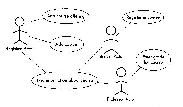
There are three actors (Registrar, Student, Professor), and there are five use cases. The "Find information about course" use case is vague and probably the three actor types can find out different information from each other. They are not typically involved in the same instance of finding out information about a class, so the example could be better.
The next figure illustrates a bunch of more exotic use case diagram items, namely actors and use cases that use or extend other actors and use cases.
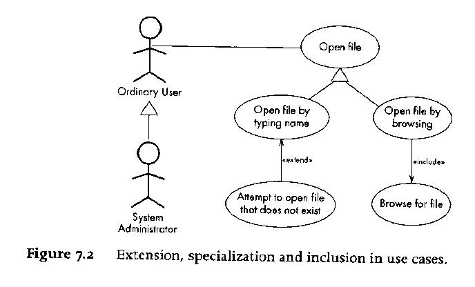
Given that UML is a diagramming notation, its ironic that the main thing about use cases are the use case descriptions. It is easy to omit one interesting category of actor in use case diagrams, namely: external system actors. A computer program may interact with external entities that are not humans; they may be remote database servers, for example.
The Bruegge textbook, as well as Figures 11-1 and 11-2 of the Unicon book give some more examples of use cases.
Announcements
- ssh+svn tricks.
- This part is different than how CVS does it, so I am having to learn along with you.
-
Group name: cs383_svn created, but our sysadmin Larry has this to say:
An old account existed for Benjamin Blaker that I was able to move forward,
so I reset his password and notified him.  I was able to create a new
account for Yik Chun Chau and I sent notification of the account (login) and
password.  I was unable to create or find accounts for Roseanne Sands and
Stephen Fischer. If you can find out the VandalWeb IDs (ala abcd1234) I can
create accounts for them and notify them.

It is possible some of the students have not tried to log onto wormulon yet,
so they may not know if their passwords work. If they can't get on - just
have them send me an email and I'll reset the passwords.
Lectures 9 and 10 by Ziad.
Lecture 11 was spent by students working in groups on requirements analysis.
Where we are at: you are finishing up and turning in your first pass at requirements analysis. As of 11am, 7 people had added their names to the svn repository. We need to move forward with some lecture material; there will be another round of requirements analysis, after some feedback, for you to refine your ieas.
Overview of Projects
Software engineering applies to small projects, but matters more for big projects.- Dividing the Labor
- Scheduling delivery of various parts of the system
- Where Does the Buck Stop?
- How do we document bugs?
- How do we evaluate the system?
- How are requirements to be documented?
- Who talks to the client?
Consider Figure 3-2, one of the dumbest statecharts I have ever seen. Still, it conveys information about major project phases.
Project Communications
- Problem Inspection - gather information about the problem
- Status meetings
- Peer reviews
- Client / Project Reviews
- Releases
- Requests for clarification
- Requests for change
- Issue resolution
Team Organization
Hierarchy vs. peer-based vs. liaison-based organizations. How do teams talk to other teams?Roles
Examples: system architect, object designer, implementor, tester... There are different kinds of roles, which relate to management, development, cross-functional, and consultant responsibilities.Schedule
This is harder than just developing a linear sequence: in a large team effort, multiple things must be developed in parallel, and various tasks cannot be started until others are completed. Gantt and PERT charts are two ways to present this information, one with a strong horizontal time axis, and one without.Analysis - What Else Besides Use Cases
This week we are moving on into Object-Oriented Analysis. Having studied the application domain (well, some of you have), it is time to produce an analysis model. "Structure and formalize the requirements".The analysis model is sometimes viewed as a three-part chorus: "functional model", "object model", "dynamic model".
At this phase, we start talking about objects in more detail, still focusing on the application domain, not the implementation. Domain objects can be classified into three general categories: entity, boundary, and control. You can use <<stereotypes>> to identify a class' category. Alternatively, you could color code them or group them physically, maybe separating the categories using dashed lines or some such.
Identifying Entities
Red flags:- Real-world entities that the system tracks
- Real world activities that the system tracks
- Terms developers/users clarify/explain in order to understand the use case
- Recurring nouns in the use cases
- Data sources or sinks
| POS | Model | Example |
|---|---|---|
| Proper noun | instance | Alice |
| Common noun | class | Field officer |
| "Doing" verb | operation (method) | create, submit, select |
| "Being" verb | inheritance | is a kind of, is one of either... |
| "Having" verb | Aggregation | has, consists of, includes |
| Modal verb | constraints | must be |
| Adjective | attribute | incident description |
Boundary Objects
Red flags:- gui controls needed for the use case
- forms the users need to enter data into
- notices and messages the system will use to inform the user
- different actors' terminals (windows/connections...)
- do NOT UML-model the actual screenshots (sketch or use an interface builder)
- use end-user terms for describing interfaces, not implementation terms
Control Objects
Coordinate boundary and entity objects. "Manage" the forward progress through a use case. One control object per use case, or maybe per actor in the use case.Sequence Diagrams
Kind of redundant with use case descriptions, but the shift in perspective often identifies additional classes and methods. See figures 5-8 through 5-10 (Bruegge).- First column = actor who initiated use case
- 2nd column = boundary object used to initiate
- 3rd column = control object in charge of use case
- <<create>> 3rd from 2nd; additional boundaries from 3rd; entities probably do not get created except in specific situations (they are usually "persistent" from some prior use case)
- entity objects get accessed by others, they do not access non-entities
CRC Cards
| class | |
|---|---|
| responsibilities | collaborators |
|---|
Class Diagrams
Class diagrams are the "meat and potatoes" of object-oriented analysis and design. We will begin our discussion of them today, and continue next week. Class diagrams describe more detailed, more implementation-oriented things than use case diagrams.Class diagrams can present varying levels of detail about the classes in them. Some class diagrams may have nothing more than the class name for each class; others may hold the full list of fields and methods. When more space is taken by class details, there is room for fewer classes per diagram, so you often have "overview diagrams" that show many classes and their connections, supplemented by "detail diagrams" that show more information about closely related classes.
Associations
Perhaps the main purpose for class diagrams is to identify and depict relationships between objects that will be needed in the running system. An association is the word we use for such a relationship. We draw a line between the rectangles for classes to depict an assocation. There are three major types of associations:- inheritance
- aggregation
- user defined
- aggregation
Inheritance: the Un-Association
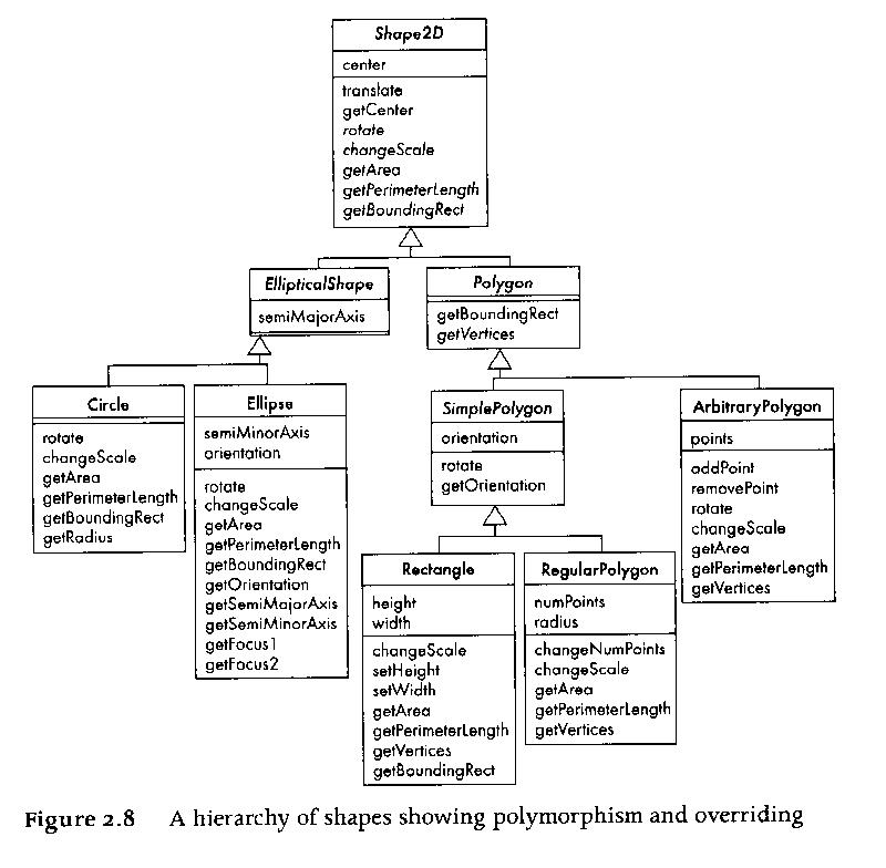
We have discussed how inheritance is not really an association, it is a relationship between kinds of things, in the design and maybe in the programming language type system, whereas associations are relationships between instances (objects) at run-time. Inheritance is so vital that many class diagrams focus specifically on a large inheritance class hierarchy, similar to a biological taxonomy of species. Inheritance is usually a static feature of a design, although there exist languages in which instances can change who they inherit from at runtime.
Here is an
example class hierarchy from the Lethbridge book (chapter 2):
Aggregation: the Simplest Association
Aggregation, the parts-whole relationship, is perhaps the most useful association of all of them. Many many complex things are made up of an assembly of simpler items. There are at least two flavors of aggregation, static and dynamic. Static aggregation is lifelong aggregation; the parts cannot exist apart from the whole, or enter or leave the whole. Dynamic aggregation is more like a team whose members can come and go. Here is an example of a massive chain of aggregations with a familiar theme: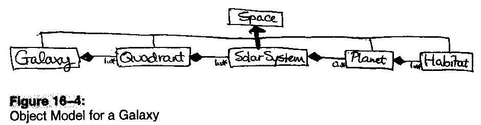
Association Details
There are many details added to associations to show more information about the relationship. Some of these details are discussed in Chapter 5 in your text.- link
- just as classes have instances at runtime called objects, associations have instances at runtime called links. Links occasionally are so important and complicated that they need their own attributes. The main information about them is usually their lifetime, and what instances they are connecting.
- multiplicity
- a.k.a. cardinality, it is the number of object instances per link instance in a given relationship
- qualifier
- some many-to-one relationships have a unique key used to traverse the association.
- roles
- the different ends of an association may have differing roles associated with them. Especially useful if both ends of an association connect the same class.
- composition
- there is a special kind of aggregation called composition, which denotes aggregations in which the component parts have no existence apart from the whole thing. The relationship is hardwired, static, or constant. Composition is marked using a filled diamond; hollow diamond means a regular (transitory, or dynamic) aggregation.
Here are some more class diagram figures from some old software engineering text (Pfleeger). One point here is that it is logical to start with a simple sketch of classes and basic relationships, and add many details later on.
As a larger example of class diagrams and associations, consider a previous semester's project. They produced two, overlapping class diagrams, one focusing mainly on cards and card decks and one focusing on characters, units, and the map. We can look at these two diagrams and consider what they did right, what needs to be changed for the campaign game. We can also work, as an example, some of the classes and relationships for the Monopoly game.
User-defined Association Examples
Here is an association you might see in a human resources application:
|
employee employer Works-for |
|
What are some example instances of this association?
Here is a more detailed version of that association:
|
employee employer * Works-for |
|
There is a multiplicity, since many people may work for the same company. But what if a given person works for more than one company?
Here is an association you might need for a geography application:
| Has-capital |
|
Now, what are some examples of this association? Give me some instances -- and their "links". To include more information in this association, we need to know:
- How many capitals can a country have?
- How many countries can a city be capital of?
- Does every country have a capital? Vice-versa?
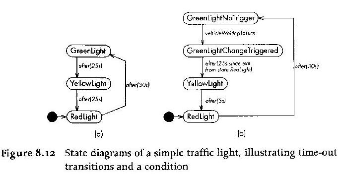
Statecharts
A statechart, or state diagram, depicts dynamic properties of a system. See p. 276 of the text. A statechart consists of- a set of states
- drawn as circles, ovals, or rectangles, with a label or number inside.
- a set of transitions
- drawn as arrows from one state to another.
- a start state, and a set of final states
Some of you may be getting an eery sense of deja vu at this point. Statecharts are a non-trivial extension of finite automata, because they have:
- instead of "input symbols", events associated with transitions
- these may be complex, synchronous or asynchronous
- events may have conditions, drawn inside square brackets
- activities
SVN Woes ... and Practices
- As of today 10/1/08, Credits.java had 9 names (not counting Drj) and Credits.cpp had 9 names.
- Java team has created a docs/ directory, C++ team hasn't yet.
- If you mess up the SVN repository, get help, don't just ignore it.
- Do exercise care with the class SVN. Practice on your own SVN repository, not ours!
- How to avoid stomping on others' work? For binary files (image files, .doc files...) SVN provides little or no help.
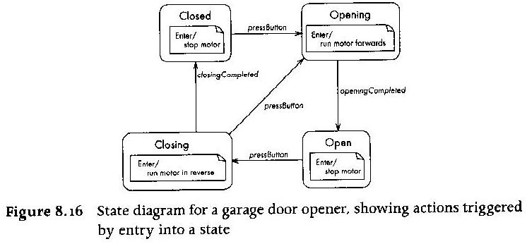
Statechart Diagram Examples
Announcements
- Engineering career fair Monday
- Monday you will also find out from my attire whether the Vandals are able to best UNR in men's football.
- Midterm a week from today
HW clarification
HW #3 really is due Monday October13. However, given the large amount of time I am giving for it, I'd like some good class diagrams, and don't anticipate giving you feedback and a re-do after October 13. I'd like everyone to do some class diagramming, enough to pass your midterm. You are strongly encouraged to (a) critique and help your teammates make your team's class diagrams the strongest set you can muster, and (b) run your class diagrams past Dr. J (via e-mail or in person) prior to the final submission, for preliminary feedback and suggestions.More Class Diagram Examples
If you google or UML class diagram examples, you will come up with lots of links like the following which maybe useful in coming to terms with UML class diagrams. However, the main way to get used to them is to practice them yourselves, which we will do in class today.
Comparing the C++ and Java team's Requirements Analysis Documents
| Attribute | Java Team | C++ Team | Winner / Notes |
|---|---|---|---|
| Pagecount | 28 pages | 48 pages. | C++ |
| Titlepage | yes | sort of | Java (better logo needed) |
| Record of changes | yes | no | Java (but granularity issue) |
| Name | JMUD | Wellspring | C++ (but why this name?) |
| References | 6 | 6 | need main UML reference |
| Product Perspective | so-so | so-so | Need more / real perspective |
| Functions | bullet list | paragraph | Unclear, sketchy |
| Constraints | bullet list | hooey | Java |
| Site dependencies | sketchy | reasonable | C++ |
| Packaging and delivery | "whichever" | "on CD's" | need strategy for packaging and delivery to public |
| User Interfaces | screenshot | table | Java. Need prototype and details, think about usability |
| Section Numbering | ok | jumped shark at 2.6.11 | Java |
| External interface requirements | awol | incomplete | C++ |
| Use case Diagrams | 4, good, 1 major complaint | 4, good, 2 major complaints | |
| Use case Descriptions | 16 | 39 | C++ |
More Statechart Examples
Next week we will work on statechart examples relevant to your semester project.
Ethics and Social Implications of Computing Technologies.
Review papers at Dr. J's CS Ethics page.Goldwater
Outstanding sophomores and juniors should be aware of the Barry M. Goldwater Scholarship. This is a national scholarship that supports undergraduates who are majoring in the natural sciences, math or engineering. The award amount is for up to $7500.00 to pay for the final year or two of undergraduate education. This is also a scholarship that UI students have been quite successful in winning in recent years. If you are an outstanding student please consider submitting an application. NOTE: the internal deadline for applications is Monday, November 12th. Additional information on the Goldwater Scholarship is available at:http://www.uidaho.edu/honors_program/UIgoldwaterinfo.htm
When is Open Source, not really Open?
Compare major open source licenses. GPL, LGPL, BSD, MIT, etc.Homework Comments (from past years)
- Use case descriptions were mostly good, many UML diagrams had problems.
- A lot of great creative work contributed.
- Use case description common problem: vagueness
- UML diagram common problem: legibility
- Use case common problem: some things in ovals aren't really use cases
- Class diagram common problem: associations not defined.
- Class diagram common problem: inheritance or aggregation abuse
- Use case descriptions' arbitrary limits need to come from somewhere
- Use case descriptions' scenarios (steps) often contain preconditions or other extraneous matter.
- Do not cite our system as one of its own actors
- Do not describe development process using use cases*
- Do not write a use case for a non-action or failed action
- Better to gray out or not mention things user isn't eligible for yet, rather than put emphasis on things user can't do.
- Granularity of use case: 1-2 steps is probably too small, lots of steps smacks of multiple tasks being performed.
Excerpts from Software is Hard
- add some excerpts here
Introduction to System Design
Read Bruegge Chapter 6!The line between analysis and design is a gray one. Broadly, requirements analysis was supposed to focus on what the software should do, while design should figure out how to do it. In our project, we are still figuring out our requirements, but we need to work out a design. The best we can do is: resolve any conflicts in currently-proposed requirements, make any pending decisions, document what we've identified and agreed on at this point, and call that our requirements document, realizing that it may have fatal flaws of omission or commission.
Bruegge says that our next job is to identify design goals, establish an initial subsystem decomposition, and refine that subsystem decomposition until all design goals are satisfied.
Design Goals
Bruegge is not especially helpful here, stating that some design goals come from the nonfunctional requirements, and some emerge from further discussion with the client, and that they all need to be written down. The nonfunctional requirements are already written down. The client is not a software designer, what do they know about it? We need to think "outside the text" a minute here.Subsystem Decomposition
What exactly is a subsystem? The amount of work a single developer or team can produce? This idea from Bruegge seems bad on the face of it. The subsystems should address relatively separable or independent elements within the overall system; it should be logically driven by the requirements or our ideas of how to meet those requirements. But it is the case that one of the consequences of subsystem decomposition is to identify pieces that persons or teams can focus on in detail.A subsystem is characterized by what services or interfaces it provides to the rest of the application.
Object Oriented Design: Adding Detail
You can view object oriented design as a process of adding detail to class diagrams. We will look at as many examples of this process as we can.For detailed design, we need to reorganize/regroup and assign teams to go into the details of various aspects of content delivery and activities.
We should divide the labor right now for work on design, adding details and corrections to your project analysis, and merging ideas you find in other folks' homeworks #2-3.
Make sure your names are on any submitted course documents. In fact, I need to know who did which parts of which documents, so I don't lump everyone together under the same grade. If you are asked to prepare part of a document you don't understand, better ask your classmates and/or instructor what is needed for that part.
Vertical and Horizonal Teams
Last class we identified major technical categories (UI, database, etc.). Dr. J mentioned the possibility of organizing around functional tasks instead, each team being responsible for a set of related use cases.- Administration team (MikeB, BrandonArp, RusselF, ChrisS, Serge)
- account creation and management, user and teacher reporting
- Navigation team (Justin, JoeyG, DanM, Trevor, AnthonyK)
- integration / user interface / map / activity selection
- Library skills team (DeanT, AndrewG, JosephE)
- develop content / activities / NPC's related to library skills
- Data (tutorial) team (MarkC, ChrisF, KaneG)
- develop content / activities / NPC's related to binary representations
- Algorithms team (AlexO, Curt, KC, Shruti, BrandonM)
- develop content /activities / NPCs related to logic and sequencing of algorithms and problem solving
- Help / chat team (NateE, BenS, Patrick, BennyH)
- develop automated and human-based help and chat communications
User Interface Design
By the next round of turnin, we will need to establish a fairly complete user interface design for things like the main screen. User Interface Design is the subject of an entire course (CS 485) and for our purposes we will have to settle for a rudimentary and primitive introduction.User interface design starts from what tasks/activities the application is to support. You probably will discover a few tasks in this phase that requires a dialog for a task we haven't identified previously. But mainly we need to design dialogs and sequences of actions to perform specific tasks in use cases.
Aspects of User Interfaces
- look
- this is the most obvious part of user interface design, but not the most important part
- feel
- this is like: what clicks perform what operations. how many clicks does it take. does it feel like you are directly manipulating the objects on the screen, or does it feel like you are following a long sequence of orders you receive from the program.
- metaphors
- users can quickly learn an unfamiliar task, or quickly interpret an unfamiliar graphic, if a familiar metaphor is used. Examples: "desktop metaphor"
- mental model
- a user interface provides the user with a particular mental model of how they view the system. designing that model will determine many aspects of the user interface (what info to show, what tasks to support)
- navigation rules
- navigation through large structures which don't all fit on the screen is a central issue for many (most) applications.
A few Obvious User Interface Tips
- Minimize # of clicks for common tasks
- Provide all the information that's needed on a single screen
- Strive for "direct manipulation"
- Modeless is usually better than modal
- Be familiar and consistent with other applications
Interpersonal Communications: Some Rules of Engagement
- 1. Respect your classmates, even when you disagree or they are wrong.
- "Treat others the way you would like to be treated" - Jesus. I am not impressed, and will not tolerate for long, group "leaders" who disrespect their teammates publically. If you have a problem with one of your team member's contributions, discuss it with them privately. If you cannot resolve it through polite discussion with the individual, discuss it RESPECTFULLY within your group, and if there is a problem that can't be resolved internally, see me. Part of your grade will be based on whether I determine that you respected your classmates or not.
- 2. Accept group decisions even when you disagree.
- "The Needs of the Many Outweigh the Needs of the Few...or the One" - Spock. There has to be some mechanism for making decisions, whether it is democracy, dictatorship, or whatever. Those decisions should be made based on what's best for the group, not what makes an individual look good.
- 3. You must include all group members in decisions.
- I want to hear no more team members who are surprised about something that affects them.
- 4. You should do your best to contribute to your team.
- "From each according to his abilities" - Marx. The easiest way to fail this course is to not contribute to your team. If you do your best, make your contribution, and the team discards it, that is not your problem or fault. If you don't do your best to help your team succeed, don't be surprised at the grade you get.
- 5. E-mail is not a good medium for resolving problems.
- I have found through many long years that e-mail does not work well at conveying emotions. Using e-mail to try to resolve problems can easily make them worse. Of course, sometimes you have no choice, but basically e-mail is easily misinterpreted. Human faces and intonation are lost, and people do not type as well as they talk. When there is a problem, your best bet is to e-mail to setup a meeting to discuss it. Your next best bet is to think, and rethink, what you are planning to send by e-mail. Ask: how will this person react to this e-mail? Have I respected them? Will they understand my situation? Will they feel I am attacking them, or trying to help?
From: ralphThis e-mail may have accomplished a certain motivational goal, but it did not improve the working relationship between sender and recipient.
To: cjeffery
Date: Wed, Apr 22
Subject: CarpingI'm more than a bit tired of beating you about the ears in hopes that you'll rearrange your priorities, work habits, or whatever it takes to get your research on track.
I'll assess the situation in a couple of weeks. If I'm still not satisfied with your progress, I'll put it in writing.
Why are interaction and collaboration diagrams useful?
These UML diagram types help connect the use cases and classes. Each scenario (== sequence of steps for a use case description) can lead to a collaboration diagram. The collaboration diagrams in turn help identify missing classes, methods, and associations for class diagrams.
Design Buzzwords and Vague Concepts
Here are some buzzwords and ideas that relate to design:Design methods
- 1. modular decomposition
- top-down breaking up function into parts
- 2. data-oriented decomposition
- top-down breaking up information into parts
- 3. event-oriented decomposition
- identifying what changes are to be made, and when they occur
- 4. outside-in design
- blackbox I/O orientation
- 5. object-oriented design
- relationships between data
Things that get designed
- 1. Architecture
- interaction between programs and their environment, including other programs
- 2. Code
- algorithms and data structures, starting with equations, pseudocode, etc.
- 3. Executable/package
- how is this system going to be installed and run on user machines?
Some common breakdowns
- poor prioritization
- failure to consider constraints on the solution (missing requirements)
- failing to perform mental simulations of complex multi-step activities
- failing to track and return to subproblems which aren't solved yet
- failing to expand/merge/integrate subsolutions into a complete whole
Team Meeting Day: Wednesday
Please turn in an attendance sheet. Friday will be a guest lecture on the collaborative virtual environment, given by Mr. Hani bani-Salameh.
"Good" Design
- Low coupling
- Coupling refers to the interdependences between components.
Components need to be as independent as possible.
The book defines many kinds of coupling, including content coupling,
control coupling, stamp coupling, and data coupling.
- High cohesion
- Cohesion refers to the degree to which a component is focused
and connected internally (it is almost "internal coupling").
Bad cohesion has a single component doing unrelated tasks.
Bad cohesion may coinside with lots of duplicate code (same
thing repeated with slight changes for different tasks).
The book defines levels of cohesion: coincidental, logical,
temporal, procedural, communicational, sequential, functional.
- Minimal complexity
- There are several types of complexity, but in general, complexity
is bad, and the goal is to minimize it while meeting requirements.
Most of the complexity measures that are out there measure the
complexity of code, but we are talking about design right now.
Designs that are complex, or designs that poorly address the
application domain and requirements, lead to complex code.
Bad programmers can of course create complex code from even good designs.
Good/Bad Design Examples
- Vince Kellen's
Coupling and Cohesion Examples give examples of bad cohesion,
indicated by excessive module length/size, along with other goodies.
- Lethbridge and Laganier have an on-line "knowedge base" including a set of
design principles and a
software quality section
- Wikipedia entries on coupling and cohesion
give some concrete examples
Comments on Homework
Homework #5 submissions are posted.
- Are you a team?
- Did you meet with your team enough to sew your homework #5 together
into a coherent document? Division of labor is great, but integration
is harder and equally important. It will be part of your grade on
future team homeworks from now on. It requires scheduling and not
everyone-goes-and-does-their-part-the-night-before-its-due.
- Produce a readable document
- I have to be able to read your hard copies, I really mean it! If you
can't format your diagrams to fit the page, or print a lot of text so
small I can't read it with my glasses on, or don't have enough toner
in your printer: fix it.
- Produce an editable, electronic document
- Hand-drawn sketches are welcome. Whose job is it to scan them in
so that they are part of the project ? .jpg or .pdf files are
welcome. For us to be able to edit, we need the .dia or other
source files used to produce the .jpg or .pdf if there are any.
- Avoid "buzzword infection"
- Students learning software engineering or UML are exposed to many new
terms. When writing software engineering documentation, keep the
technical buzzwords out of your application domain descriptions unless
they really belong there. Example: in use cases you learn about actors,
so in your descriptions of the application domain, the word "actors"
starts being used to refer to many non-actor things.


