COPYRIGHT NOTICE. COPYRIGHT 2007-2015 by Clinton Jeffery.
For use only by the University of Idaho CS 383 class.
Lecture Notes for CS 383 Software Engineering
Reading
Please obtain your copy of the text book (Sommerville, 10e) as soon
as possible.
Introduction to Software Engineering
- What does "software engineering" really mean?
- Many expert computer scientists argue that this term is a misnomer.
This course is really about: tools and methods that
are useful for larger-scale software development projects.
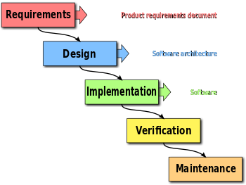
Software Lifecycles
- waterfall model
- The original proposed lifecycle for engineered software.
Sequential. Requirements analysis,
design, implementation, testing, and maintenance phases.
 (Wikipedia)
- spiral model
- An iterative waterfall model, proposed by Boehm. The waterfall is
repeated in sector 3. The graphic suggestion 75% of the spiral is now
in non-waterfall activities is probably misleading.
 (Wikipedia)
- agile model
- A priority-driven iterative model. Waterfall phases are freely mixed
into a work schedule organized aroound a sequence of "sprints" and daily
"scrums".
 (LinkedIn/Hamzeh AbuZaid)
Expectations Management
A brief discussion on expectations management: this class' primary goal is
to teach and gain experience with software engineering concepts, tools, and
methods. The goal is not a finished working product at the end of the
semester, it is more like: a properly engineered (i.e. documented) working
prototype.
Course Perspective
I believe that you learn by doing, and that you
learn more and better by doing a larger project than you could do by
yourself or in a small group.
Ideally this course would cover the entire software lifecycle, and you
would learn hard truths about coming into a project during the middle
of development. You would have to read and understand others' documents,
ask questions until it makes sense, and make an important contribution
in a short span. In practice, it is hard to achieve this in a university
setting. Don't expect this knowledge to come without a price, whether
you learn it here or on the job someday.
Recent (Dr. J Dynasty) History of this Course
In the past few years, CS 383 has undertaken with varying degrees of
success the following projects.
- TBDCRPG
- A tile-based dungeon-crawling role playing game.
- L33t
- An educational software framework which was to teach pre-college students
basic principles of computer and information science.
- Wellspring
- A collaborative software engineering diagram editor.
- Arkham Horror
- A complex, cooperative board game.
- The Table
- A (hardware+software) platform for computer-assisted board games.
- Gus
- A Management System for Campus Groups & Clubs.
- Freedom in the Galaxy
- An adaptation of a Star Wars-like science fiction simulation game.
- Swords & Sorcery
- An adaptation of a fantasy simulation game parodying D&D and others
Discussion of Project Topics
CS 383 has contradictory requirements
- Project needs to be the "right size and shape".
- Bigger than you can do on your own. Small enough we can complete it,
at least somewhat.
- Project should be Interesting and Fun
- By definition, that means it uses networking and graphics a lot
- Project can require no prior expertise on networking and graphics
- Those classes are not prerequisites. Consider this a warmup.
- Accreditation Requirements
- We must spend most class time on lecture material, not just the project
Constraints on the Project
Size and shape constraints will exclude many
fine potential software projects you might wish you could do. The constraints include:
- Application should have many distinct user tasks, such that each
student on team can design several of them (55, or maybe 110 things
you can do with the software).
- Application domain already familiar to students or easily learnable by
the whole class.
- Requisite API's (database, network, graphics, etc) already familiar or
easily learnable by the whole class.
- Can develop for target platform on CS lab machines (additional student
machine platform support strongly desirable)
What I Learned from (Previous Iterations of) CS 383
- Python is poorly suited to software engineering
- A brilliant team with expert Python programmers can
experience a lack of optimal success of they don't design
or communicate well.
- Need to start using agile methods from the beginning
- We will do homeworks this semester in terms of lists of assigned tasks
Weekly Activity Reports.
Starting with this (next) week.
- Instructor needs to be (semi) dictatorial
- We need both instructor- and student-leadership.
Leaving it all up to you is unwise. Students need to
recognize the burden that comes with leadership.
- "Smart" does not imply (good leader | productive student | team player)
- There are different kinds of "smart"
- "Bossy" does not imply (good leader)
- Many teams let whoever is loudest win. This is not always good.
- Cliques are hard to avoid, and damaging
- Hidden costs associated with sticking close with your buddies
- Language familiarity seems to be important
- Especially when time is of the utmost
- Design is more difficult than coding
- Counterintuitive. Also: bad design precludes good code.
- Early rounds of coding needed to feed design process
- "rapid prototyping" is usually where C++ and java stink it up.
- We need competition
- Although I would prefer a single class-wide effort, it doesn't
always work optimally.
- We need large teams and shared assets
- Small teams do not let you learn some course topics.
- Communicating and committing are more difficult than technical issues
- Counterintuitive.
- Integration is more difficult than designing and coding your own stuff
- Therefore it takes time.
- All modern OO languages have ugly "warts".
- There is a "semantic
gap" between clean/abstract OO as seen in designs, and ugly OO
provided by programming languages.
- Don't run two independent projects
- We cannot split the class time like that.
- Don't elect a new rotating boss man
- Nobody will know where the buck stops. Dr. J suggests instead
that your team adopt the rules of pirate captaincy. (Elect a
boss, then live with that person's management style. Respect
authority. Mutiny only when your project success or grade is at stake.)
- Enact some system to force teammates to meet weekly goals.
- Can't be all carrots, must have some sticks.
- Sundays are a poor day for team meetings
- They work fine for some, fine for awhile, hard to keep attendance up.
- Need 1+ group technical sessions each week, not just group/mgt. meetings.
- Same-time tech sessions, maybe same place not always necessary.
- Group meetings need to start on time and stay on task
- Many of your teammates do not have time to goof around
Lecture 3
Discussion and Vote on Project Candidates
Notes:
- Unicon Portable Help System removed due to it being in Unicon.
Our preferred languages for this class are Java or C++.
Languages
There is the language we will use for our software design (UML),
the language we will use for our documentation (LaTeX), and the
language we will implement with (probably Java). There are some
considerations and trade-offs involved in our selection of languages.
- UML is an industry standard and CS major should be familiar with it
- LaTeX is ASCII-human readable and thus amenable to use with
revision control systems such as SVN or Git.
- Java is valuable on resumes, similar but easier than C++, and has
a good track record. C++'s main advantage would be: staying fresh
for CS 445 prep
Lecture 4
Basic Concepts for the HW
- use cases and their descriptions
- the first step in requirements is to know what tasks the user
will perform using the software
- agile methods #1: sprint
- as defined here, a sprint consists of a interval of time,
usually 1-2 weeks, with a concrete set of goals to which
each team member commits. In between each sprint is a sprint
planning phase, including individual progress reports and
a planning meeting.
Use Cases and Class Extraction
You can identify classes from a software specification document by looking
for "interesting" nouns, where interesting implies there are some pieces
of information to represent in your application, and operations to perform
on them. You can also identify classes by developing use cases from the
specification document.
Lethbridge defines a use case as:
A use case is a typical sequence of actions that an actor performs in
order to complete a given task.
I would say: use cases are formatted descriptions of "discrete"
tasks. By "discrete", we mean an individual standalone thing a user does
while using the system.
If you look through the tasks mentioned in a specification document, you
can identify a set of candidates.
Example candidate tasks for a "wargame":
- Combat
- Roll dice
- Move pieces
- Perform the Missions Phase
Example candidate tasks for the Parker Brothers game called Monopoly:
- Buy property
- Roll dice
- Move piece
- Count money
Example candidate tasks for an online collaborative IDE:
Entire books have been written about use cases.
Use cases are also described
in Chapter 11 of the
Unicon book; some of today's examples may be found there.
Use Cases: Terminology
- actor
- role that an external entity plays in a system
- use case (or just "case")
- depiction of some aspect of system functionality that is visible
to one or more actors.
- extension
- a use case that illustrates a different or deeper perspective on another use case
- use
- a use cases that re-uses another use case.
Now we will expand on the discussion of use cases, use case diagrams, and
look at examples.
Use Case Descriptions
Drawing an oval and putting the name of a task in it is not very helpful
by itself, for each use case you need to add a detailed use case
description. Your first homework assignment is to "go and do this" for
your semester project.
Section 7.3 of the text explains the format of use case descriptions. Each
use case has many or all of the following pieces of information. The items in
bold would be found in any reasonable use case description.
- Name
- The name of the use case.
- Actors
- What participants are involved in this task.
- Goals
- What those people are trying to accomplish.
- Preconditions
- The initial state or event that triggers this task.
- Summary
- Short paragraph stating what this task is all about.
- Related use cases
- What use cases does this use case use or extend? What uses/extends this use case?
- Steps
- The most common sequence of actions that are performed for this task.
Lethbridge divides actions into two columns: user input
is given in the left column, while system response is
given in the right column. The two column format is
optional, but saves on paper and may improve clarity.
The steps are numbered, so there is no ambiguity in using
both columns on each line.
- Alternatives
- Some use cases may vary the normal sequence of steps.
- Postconditions
- what does this task produce?
Use case descriptions, examples
A simple generic use case for a "file open" operation might look like:
Open File
Summary: A user performs this task in order to view a document.
The user specifies a filename and the document is opened in a new window.
Steps:
- Choose "Open" from the menu bar.
- System displays a File Open dialog.
- User selects a filename and clicks "OK".
- System closes the dialog and opens the file in a new window.
Alternative: If the user clicks Cancel in step 3, no file is opened.
|
Lethbridge-style two column format is nicely motivated in the following
example, which has enough steps to where two columns saves enough
space to matter. When you start having trouble fitting the whole use case
description on a page, there are substantial benefits to a compact format.
Exit parking lot, paying cash
Actor: car driver
Goal: to leave the parking lot
Precondition: driver previously entered the parking lot, picked up a ticket,
and has stayed in the lot long enough that they must pay to leave.
Summary: driver brings their vehicle to an exit lane, inserts their ticket
into a machine, and pays the amount shown on the machine.
Related use case: exit parking lot, paying via credit card.
Steps:
| 1. Drive to exit lane, triggering a sensor.
| 2. System prompts driver to insert their ticket.
|
| 3. Insert ticket.
| 4. System displays amount due.
|
| 5. Insert money into slot until cash in exceeds amount due.
| 6. System returns change (if any) and raises exit barrier
|
| 7. Drive through exit, triggering a sensor.
| 8. Lower exit barrier
|
Alternative: User crashes through exit barrier with rambars on front of truck
in step 1. (just kidding)
|
The following example (by Lethbridge et al) gives you one more look at use
case descriptions. This one is for a library management application.
Check out item for a borrower
Actor: Checkout clerk (regularly), chief librarian (occasionally)
Goal: Help the borrower borrow the item, and record the loan
Precondition: The borrower wants to borrow a book, and must have a library
card and not owe any fines. The item must be allowed for checkout (not on
reserve, not from reference section, not a new periodical, etc.)
Steps:
| 1. Scan item's bar code and borrower's library card.
| 2. Display confirmation that the loan is allowed, give due date.
|
| 3. Stamp item with the due date.
|
| 4. Click "OK" to check out item to borrower.
| 5. Record the loan and display confirmation that record has been made.
|
Alternative: the loan may be denied for any number of interesting reasons
in step 2 (see preconditions).
|
Lecture 5
(most of class spent discussing HW#1)
(How to Estimate) What's Feasible?
After we have a set of use cases (with descriptions) for our project, we
can use it to form a "version 1.0" estimate of our system's function
points. We can, from that, estimate time and cost of developing the
system.
Perhaps this might be the 2nd type of thing you measure about a forthcoming
or under-construction software project (after "# of use cases").
- # user-input activities
- # user-output views
- # user "queries" (for database apps)
- # of data files
- # of external interfaces
Weight each of these; perhaps just designate as "simple", "average", or "complex".
Sum of weights = "function points" of program.
We wil have to come back to this, because we have more urgent content to
work on.
Agile Methods and Scrum
- Intro to scrum and sprints.
- Note: how many do not have the text yet?
- If you do not have the text, it is not an emergency (yet).
- Please obtain the text as soon as you can, follow the
class presentation, and ask your teammates questions as needed.
Lecture 6
Use Case Description Tip
Maybe I need to move this comment earlier, to deliver in time
for use on HW#1. In the meantime, consider it a thing to check and
fix if need be, based on past CS 383 experience.
- Something can't be both a precondition, and a step
- If it was a precondition, it was already true before the use case.
What else did you find confusing or tricky about use case descriptions?
Some Project Considerations
- Should we stick with 4 teams? Do more? Fewer?
- Rationale for more: common "wisdom" that too large a team will allow
folks to freeload.
Rationale for 4 teams: scrum book recommendation as to maximum
scrum team size.
Rationale for fewer (like 2 or 3): larger team experience gives unique
insight into communication and coordination challenges in software
engineering.
- Shared functional requirements, not team-separate.
- Rationale:
common requirements means time spent working on them in class will be of
equal interest to all parties.
- Team composition
- Instead of randomizing, should I in future distribute
the GPA's equally among the three teams. Do you have a better suggestion?
A buncha famous software engineering snake-oil salesgurus all signed the
following inarguable statement:
We are uncovering better ways of developing
software by doing it and helping others do it.
Through this work we have come to value:
- Individuals and interactions over processes and tools
- Working software over comprehensive documentation
- Customer collaboration over contract negotiation
- Responding to change over following a plan
That is, while there is value in the items on
the right, we value the items on the left more.
Agile Methods Tips
Gamedev.net once posted (associated apparently with gdc2010) an interesting
article on agile methods, which has since disappeared into the ether. What
we have left are the following observations about doing agile methods well.
See if any will help in your sprints this semester.
- Instead of "completion of developer tasks", focus on
delivery of features.
- Agile teams spend more time on planning than
traditional teams. Expect and budget time for that.
- Allowing too much uncertainty into a project can reduce velocity.
This is our key challenge right now
- Developers are responsible for what they achieve each sprint.
- Do things that add value.
- Get things done in a constrained time-box.
- Know your capabilities...and your limitations.
- Communications is essential! Keep 'em frequent, keep 'em short.
Since different teammates have different styles,
parties need to agree on a medium and frequency of communication.
- Have a central shared place (e.g. wiki) for project information
Scrum
The term scrum derives from a part of the game of rugby in which teams
lock arms and put heads together. As an agile method it refers to a way
of conducting planning meetings. There are typically two kinds of meetings:
- "daily scrum"
- a short meeting, held frequently, amongst the team
- "sprint"
- a longer meeting, held every 1-2 weeks, to deliver features and set
goals for the next sprint
Our implementation:
- daily=15 minutes every other day, MWF
- sprint=25 minutes, every 2 weeks
Scrum Roles
These roles are primarily evident during the planning meetings for each
two week sprint.
Adapted from Scrum Alliance.
- product owner
- for our class purposes, this is me. decide what work will be done each
sprint. maintain the backlog.
- development team member
- deliver increments of functionality each sprint. "they have the
responsibility to self-organize to accomplish each sprint goal".
product owner says what is to be done, devteam members forecast what
can be done in one sprint, and decide how/who are going to do what.
- scrum master
- "servant leader" who helps the team follow the process. Scrum masters:
- "evolve the definition of Done".
- help find and implement whatever technology and methods are needed
to get to Done each sprint.
- remove impediments
- facilitate meetings, help team members
Creating an Initial Backlog
Adapted from
Fear No Project
- "Product Backlog" is almost: list of (not-finished-yet) Functional Requirements
- Acknowledges Changing Requirements throughout project
- SSRS Functional Requirements Section === backlog ++ completed items.
Hopefully, backlog shrinks as completed items list grows long
- The first backlog is "vision, analysis, and marketing promises"
- Oh by the way, everything needs to be prioritized.
- Responsibility of the product owner (darn!). But as an educational
exercise, you should expect to build and maintain this document (huzzah!).
Scrum "Daily" Meetings
We start these next week.
- 15 minutes
- Each person on the team reports:
- What I did yesterday
- What I will do today
- What impedes me?
- "yesterday" is really: since the last meeting, i.e. 2-3 hours of work
Sprint Meetings
For the purposes of this class, a sprint meeting consists of three parts.
Per the feedback from last time, it is recommended that this semester we
try spreading the sprint meeting over two classes every two weeks.
Sprint Day 1
- Review (N*5 minutes)
- Except on the first one, review the outcome of the past
sprint. <= 5 minutes per team, in front of class.
Show/Demo finished backlog items (deliverables).
Graded on technical content and communication/relevance/value.
- Reflection (2 minutes)
- Answer two questions: What went well? What could be improved?
Process improvement is all extra credit.
Sprint Day 2
- Planning (25 minutes)
- 23 minutes in your team, updating requirements and backlog. 2 minutes
per team to report and/or negotiate with your instructor on items
committed to complete for the next sprint.
The instructor will often provide one or more Required elements for the
following week's sprints, to go along with whatever team-specific goals
you formulate.
Lessons from past class' mis-application of scrums and sprints
- Its bad to not hear reports from all members in a scrum.
- Scrum should not be just an informal chance for the loud people to talk.
- sprint planning needs more time!
- Possible solutions: switch to 75 minute class periods (bad, fewer scrums)
or spread sprints across two classes instead of trying to get them done
in one 50 minute session.
- scribe/recorder should place decisions/work assignments/attendance records
in a public place the whole team can see.
- fact of life: some times folks have to miss
lecture#7 began here
Comments on HW#1
- Overall, good work
- I (almost always) want PDF. Don't resubmit if your .tex is adequately
included in group's PDF. Do resubmit if your PDF was a depiction of
your .tex source code instead of the output pdflatex for that document.
- Grades on HW#1 will be somewhat gentle. Future homeworks will be harsher.
- Latex tips: ``...'' not "..."
- .docx is OK for individual work, but I do actually want you to learn
some LaTeX, it is more git-friendly.
- .zip is OK for .tex+image files, but leave PDF as a separate submission
Yeah, due in a week.
Comments on Project Planning Tools
- Many softwares to run projects
- Some softwares may have specific support for Agile
- One student: "Can we Jira? Because...SEL", or maybe Phabricator
- Spring Backlogs might be managed with list-oriented tools like
Trello, or Emacs "Org Mode"
- Then there are Microsoft Project and its clones, e.g. OpenProj, ProjectLibre, Gantter
- It is not my intention to mandate which tool(s) your team uses,
but I recommend that teams evaluate and select one.
- Lots of other tools and notations in this class are higher priority.
- Will matter more when we have permanent teams.
Use Case Diagrams
One reason to do a use case diagram is to summarize or catalog
what tasks are part of the system; a sort of table of contents for the
beautiful set of use case descriptions that you should write.
But the main reason
use case diagrams exist is in order to show who does what, when different
users (actors) participate in different (overlapping) tasks. If you only
have one actor, or there are no tasks in which multiple actors interact,
there may be no reason that you have to do a use case dialog.
Consider the following figure from a book by Lethbridge.
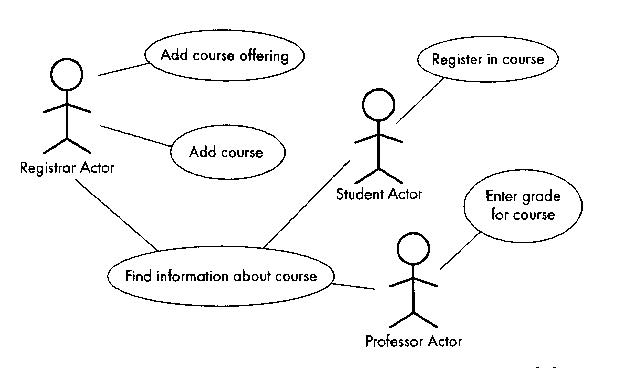
There are three actors (Registrar, Student, Professor), and there are
five use cases. The "Find information about course" use case is vague
and probably the three actor types can find out different information
from each other. They are not typically involved in the same
instance of finding out information about a class, so the example could
be better.
The next figure illustrates a bunch of more exotic use case diagram items,
namely actors and use cases that use or extend other actors and use cases.
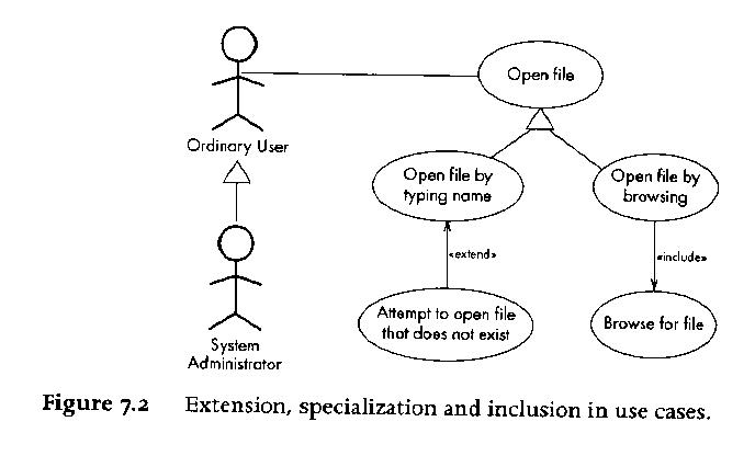
Given that UML is a diagramming notation, its ironic that the main thing
about use cases are the use case descriptions.
It is easy to omit one
interesting category of actor in use case diagrams, namely: external system
actors. A computer program may interact with external entities that are not
humans; they may be remote database servers, for example.
Figures 11-1 and 11-2 of the
Unicon book give some more examples of use
cases.
lecture#8 began here
Reading Assignment
Sommerville Chapters 1-4. You are particularly responsible for:
- SE Code of Ethics and Professional Practice
- Waterfall and Spiral models, and Process Activities
- Pretty much all of Chapter 3.
Project Steering and HW#1 Feedback
- name: sQuire
- Less "gamey". Dropping explicit MUD and roguelike features from requirements
- More: evaluation-based. Peer review. Up/down votes on projects/people.
- user roles: admin, project owner, user
- minecraft-like server/peer structure
- "up" technologies: Docker, containers...if they actually solve a
problem for us
- "down" technologies: javaScript and its ecosystem
- Several kinds of rooms:
- world=everyone connected to sQuire, everywhere
- project=top level "conference room"
- directory within project=project membership, file manipulations, build rules
- project file=collaborative editing room
- Subscription-based subject rooms
- Users auto-enter chats from all subscribed/relevant rooms
Use Case Description Tips
- If-statements don't happen in use case steps.
- The more common (then-part or else-part) belongs as the main sequence.
- The other identifies an Alternative.
- If too many or alternatives are
non-trivial: split into multiple use cases
- While-loops don't happen in use case steps.
- Not a rule cast in reinforced concrete, but:
- Use cases are not pseudocode, they are user-eye view of system function
- Time is linear, for humans.
Use Case Diagram Tips
- Actors interact with your app
- The only way a part of the software or an object being modeled by the
system is an Actor, is if it has some agency, i.e. a mind
of its own. AND it lives in a separate process, or minimally, a separate
thread.
Lecture 9.
Requirements Elicitation Techniques
Purpose: produce a requirements specification (i.e. software specification)
document.
-
Identify functional and non-functional requirements (F+URPS) (Completeness,
Consistency, Correctness).
- Focus on the
users' view of the system, NOT the internals.
- Identify actors, scenarios,
use cases. Refine and relate use cases.
Scenarios
- Before there were use cases, there were scenarios.
- A scenario is a narrative description of what people do and
experience as they try to make use of computer systems and applications
[Carroll].
- The word is overloaded. Scenarios may describe:
- a current way things are done
- a proposed way that a future software system should do them
- a method of evaluating a system
- a method of training a user on a system.
Tying Scenarios to Use Cases
A set of scenarios may include many different instances in which the
user is really performing the same task; these get merged into a use case.
Use cases typically contain a primary sequence of steps performed in
common by any scenario in which the user is doing that task, plus a
number of exceptions or alternatives.
Use Case Writing Guide (adapted from Bruegge)
- describe one complete user transaction
- use cases are named with verb phrases that indicate what the user is doing
- actors are named with noun phrases that indicate their role
- boundary between actors and system (i.e. who does what) should be clear
- use case steps are phrased in the active voice
- 7 +- 2 is usually the maximum number of steps
- causal relation between successive steps should be clear
- exceptions are described separately
- do not describe the user interface; UI design is separate
- do not exceed 2-3 pages. Probably not even 1 page.
Scrum
- last 15 minutes of class today you get to do a scrum standup meeting
- do you remember what that consists of?
- have you elected a scrum master and a product owner?
(you will have to have one starting next week)
- elect a scrum reporter, who sends me short 1-2 paragraph scrummary
of each scrum meeting. I want: absentee list, decisions made,
any unresolved obstacles, short progress summary. Today's scrummary
should include: who is your github boss, scrum master, product owner,
and scrum reporter.
The Core Problem of Software Engineering: Complexity
Over time, this means: change. What complexity? This refers not to the
asymptotic time and space complexity of a code, although algorithmic
complexity is a crucial part of it. But software's complexity, to the
humans trying to build or maintain it, goes beyond the algorithms. There
are dimensions to it: static vs. dynamic, and control vs. data, and
more.
What ones do you know of?
- Denver airport baggage handler
- Patriot missile defense system
- Ariane 5 rocket
- Therac-25 radiation treatment machine
- Mars probe
- Power grid rolling blackouts
- The FBI's Sentinel caseload management system
- Healthcare.gov
- FAA flight controller system
- DOD payroll system.
- Toyota, and more recently Dodge, with multi-billion dollar vehicle recalls
due to software bugs that cause crashes/deaths.
What do we do about complexity? Anticipate it. Minimize it. Mitigate it.
Manage it. More on this topic later; for now, you are supposed to be aware
that it is your chief opponent --- your adversary.
Why is Software Engineering Crucial?
Because the larger a program gets, and the more features you add, the
more bugs you get. Why? Because things get too complex for us to handle.
Until we can solve this unsolvable puzzle, Moore's Law is limited or
revoked by our inability to utilize hardware, just as we are
unable to utilize our own brain (wetware).
Belady-Lehman observed:
[D. Berry, The Inevitable Pain of Software Development,
Monterey Workshop 2002]
So, Software Engineering is All About Pain
Software Engineering, it turns out, is mainly about pain.
Dan Berry, one of software engineering's luminary founding fathers,
had this to say about software engineering methods:
Each method, if followed religiously, works. Each method provides the
programmer a way to manage complexity and change so as to delay and
moderate the B-L upswing. However, each method has a catch, a fatal
flaw, at least one step that is a real pain to do, that people put off.
People put off this painful step in their haste to get the software
done and shipped out or to do more interesting things, like write more
new code. Consequently, the software tends to decay no matter what.
The B-L upswing is inevitable.
Dr. Berry goes on to give the following examples:
| Software Method | Pain
|
|---|
| Build-and-fix | doesn't scale up
|
| Waterfall Model | it is impossible to fully understand and document complex software up front
|
| Structured Programming | Change is a nightmare: patch or redesign from scratch
|
| Requirements Engineering | Haggling over requirements is a royal pain.
|
| Extreme Programming | Writing adequate test cases is a pain
|
| Rapid Prototyping | We can't bear to throw away the prototype!
|
| Formal Methods | Writing formal specification, and verifying it, may be a pain. Changing requirements is definitely a pain.
|
| Code inspections | Documentation prep for inspection is a pain; nobody wants to be inspected.
|
| "Daily Builds" | Testing, regression testing, and possibly reworking
your latest change to not break someone else's latest change is a pain.
|
My goal for this course is to maximize your learning while minimizing your
pain.
Lecture 10
HW#3: first Sprint
Weekly Activity Reports
- Due weekly on Sunday 10pm, starting a week from this Sunday
- Keep a casual log of your project time
- Spend 5 minutes/week giving an individual report on what you did
- Send to jeffery@uidaho.edu, not my gmail
- Format described in the CroftSoft WAR template
- Subject line must say exactly:
[CS383 WAR] name, date with date in mm?/dd?/yyyy format so I can file them. I promise to
delete them otherwise.
- Send text in-line, not in an attachment.
- You may (and should) include links that point at your work
(usually, in the github repository).
- purpose
- Establish a record of your contributions to the team each week.
Do you know what your personal commitments are in each sprint,
and are you doing something about them?
- graded
- from 1-4, 4 being an "A"
- format
- I need to be able to read these really easily. Plain text in the
body of the e-mail is better than an attachment.
- granularity
-
The point of weekly reports is to tell me what you
are doing; probably an upper bound ought to be 2-3 subteam members can submit
a joint report on their activities.
- redundancy
- If you do submit joint work,
I only want one copy, so if you are sharing report text, I want a
single submission with all contributors' names on it.
- persistence
-
There needs to be a better mechanism for keeping these reports, besides me
just shoving them underneath my pillow. Like: put them in a subdirectory
under your doc/ in your repository.
- sharing
- some reports contain information that would be useful if it
were visible to the entire team
- privacy
- Some reports might contain information that should be for my eyes only.
Upshot: comments and suggestions are welcome; I am going to tweak/improve
what we are doing with weekly reports.
Lecture 11
Github
My github id is cjeffery. Please add me to your teams.
Feedback on HW#2
- Tip for groups: document assembly burden needs to be shared
- Group submission assemblers report the time burden is too large,
figure out how to streamline and spread out the load.
- Time to unpack/print has to be minimized
-
- one PDF per person per assignment default
- images into LaTeX documents into PDF
- Turn in one attempt...or document the difference
- If I can't get grading burden down enough, I will revert future
assignments to single submission.
- Avoid blank lines connecting UML entities.
- use case diagrams have blank lines connecting actors to use cases,
but the lines connecting use cases to other use cases should generally
have <<uses>> or <<extends>> on them.
- Avoid mixing UML diagram types
- Rectangles/classes/major subsystems/components do not belong in
use case diagrams. Just because plantUML will do it does not make it OK.
- Put your images into latex documents
- You will have more control over what I see, and whether it is legible and
well-formatted, if your images are embedded within a PDF and preferably,
interated with supporting text that expands/explains the image content.
Some Big Concepts
- In software engineering, modeling is the art of constructing a
simplified representation of a domain, which portrays those aspects
of its essence and behavior that are needed for a given application.
- Big complex systems get modeled as a set of subsystems
- Big complex designs get drawn using multiple views
- UML relies heavily on object-oriented principles. If you have
programmed in C++ does that mean you understand OOP?
Let's expand the discussion of use cases to a discussion of software
specifications.
Per Wikipedia, what I might informally and casually call a software
specification is typically and more formally called a
Software Requirements Specification, or SRS for those of you who like
TLA's. Dr. Oman, our department's reigning software engineering expert,
calls them SSRS (Software and Systems Requirements Specification),
potentially including hardware or other aspects of the system besides
just the software.
It can be argued
that developing the initial natural language prose document is not the
software engineer's job, but instead the customer's; in practice, however,
the software engineer frequently has to help, or do the customer's job to
some extent. In any case, from an existential point of view, unless we
were to choose a project with an extant specification, we must develop one.
There are IEEE standards for requirements specifications. Wikipedia's
definition says the requirements specifications includes a set of use
cases and in this class you can say that they are a prominent part of
the requirements specifications development. Based on the IEEE standards,
we have the infamous-yet-improved
LaTeX edition of the CS 383 SRS Template.
Introduction to UML
Spend 5-10 minutes surfing
http://www.uml.org/#UML2.0
and then read the
Crag Systems UML Tutorial Chapters 1 and 2.
A supplemental (non-required) reading resource for the diagram types covered
in this class can be found in the middle chapters of "Programming with Unicon",
where object-oriented features are being presented.
UML stands for Unified Modeling Language. A "modeling language" is not
a programming language, although some efforts have been made to "compile"
UML diagrams down into code.
UML was created when 3 very successful software engineering diagramming
gurus banded together to wipe out the other 12 software engineering gurus.
Actually, there was a serious need to create a common notation; prior to
that, software engineers that worked with one guru's diagrams might not
easily be able to read or understand software designs drawn by another
software engineer who had been trained using another guru's diagrams.
In CS 383,
we care about ~4 common kinds of diagrams, starting with use case diagrams.
Most other UML diagram types would be used in specialized domains.
- use case diagrams
- document how human users and other "external entities" perform tasks
using the software system that is to be built.
- class diagrams
- document major application domain entities whose representation in the
system will include state and behavior. These diagrams document the
associations, or relationships, between classes. At implementation time,
there may be many implementation classes in addition to whatever classes
are written to correspond to domain classes and domain class relationships.
- interaction diagrams
- depict dynamic behavior and communication between objects. Generally
more detailed elaborations and special cases of the "relationships" from
class diagrams.
- statecharts
- These are finite automata, with software engineering semantics added.
There are states, events, and behavior that goes on during states or events.
Interpersonal Communications: Some Rules of Engagement
- 0. Behave Professionally
- If you intend to have a career as a computer scientist, this starts with
behaving like a professional: use no profanity, work
hard, behave ethically, be honest, and do what you say you will do.
If you can't behave professionally, you can't become a decent software
engineer: please drop the course.
- 1. Respect your classmates, even when you disagree or they are wrong.
- "Treat others the way you would like to be treated" - Jesus. This starts
with being polite and/or courteous to teammates, but goes farther. No
one should disrespect your teammate(s) publically; group leaders
should be especially careful about this. If you have a problem
with one of your team member's contributions, discuss it with them
privately. If you cannot resolve it through polite discussion with
the individual, discuss it RESPECTFULLY within your group, and if
there is a problem that can't be resolved internally, see me. Part
of your grade will be based on whether I determine that you respected
your classmates or not.
- 2. Accept group decisions even when you disagree.
- "The Needs of the Many Outweigh the Needs of the Few...or the One" - Spock.
There has to be some mechanism for making decisions, whether it is
democracy, dictatorship, or whatever. Those decisions should be made
based on what's best for the group, not what makes an individual look good.
- 3. You must include all group members in decisions.
- I want to hear no more team members who are surprised about something
that affects them.
- 4. You should do your best to contribute to your team.
- "From each according to his abilities" - Marx.
The easiest way to fail this course is to not contribute to your team.
If you do your best, make your contribution, and the team discards it,
that is not your problem or fault. If you don't do your best
to help your team succeed, don't be surprised at the grade you get.
- 5. E-mail is arguably the best medium for most asynchronous team
communications.
- See Greg Donohoe's guidelines.
Some of you millenials are more into texting or whatever, but e-mail
has a lot going for it. It is portable and multi-platform. It is
reliable and takes attachments. It lends itself to recordkeeping.
- 6. E-mail is not a good medium for resolving problems.
- I have found through many long years that e-mail does not work well
at conveying emotions. Using e-mail to try to resolve problems can
easily make them worse. Of course, sometimes you have no choice, but
basically e-mail is easily misinterpreted. Human faces and intonation
are lost, and people do not type as well as they talk. When there is
a problem, your best bet is to e-mail to setup a meeting to discuss it.
Your next best bet is to think, and rethink, what you are planning to
send by e-mail. Ask: how will this person react to this e-mail? Have
I respected them? Will they understand my situation? Will they feel
I am attacking them, or trying to help?
Example of how not to use e-mail for interpersonal communications:
From: ralph
To: cjeffery
Date: Wed, Apr 22
Subject: Carping
I'm more than a bit tired of beating you about the ears in hopes that you'll
rearrange your priorities, work habits, or whatever it takes to get your
research on track.
I'll assess the situation in a couple of weeks. If I'm still not
satisfied with your progress, I'll put it in writing.
This e-mail may have accomplished a certain motivational goal, but it did
not improve the working relationship between sender and recipient.
How to Approach Dr. J with Concerns
If you are happy with what we've been doing up to now, feel free to just
file this section in a "just in case" folder, for future reference.
My goal is to make software engineering happen.
All the requirements are negotiable. All the tools edicts are negotiable.
All you have to do is come up with a better plan, and sell me on it.
- you can speak with Dr. J privately
- you might find he is reasonable at times
- you can speak with Dr. J as a group
- Dr. J is more likely to hear a group
- you can elect a leader
- Dr. J will listen to duly appointed team leaders
Revision Control Systems
We have a lot of UML to learn, but we need to get settled on and using a
revision control system.
- Revision control systems (RCSs) are programs which track
changes to collections of files (for example, the
files that are part of a software project) over time
- you can tell who did what, and revert
to an earlier version if you get broken.
- a related genre of tool are Software Configuration Management Systems.
Configuration Management is when you integrate
Revision Control, Testing, Feature Auditing, and (OS + hardware) Platform
Adaptation and Porting.
- While SCMs are a bit too much for CS 383, revision control is life.
A Brief History of Revision Control
- SCCS
- "Source Code Control System", one of the early, proprietary revision
control systems from AT&T,
inventors of C and UNIX. Library model (check out in order to write, then
check back in) makes it difficult to overwrite someone else's code, but
does not scale very well. Cool but dangerous idea: system integration with
"make" on some Sun platforms kept you up to date automatically.
- RCS
- Early open source revision control system aptly named "Revision Control
System". Library model. Set of many separate cryptic commands
("ci", "co", etc.)
- CVS
- "Concurrent Versioning System" is the open source RCS that
defined the 2nd generation. Everyone can edit files at once, it is when
you try to check in changes that things get exciting.
- SVN
- Subversion is almost just a better CVS.
- Git
- A third generation of these systems has emerged. Git was written by
Linus, the inventor of Linux, giving it an unfair marketing advantage.
- Mercurial
- Another third generation revision control system is Mercurial (Hg).
It is said to be much faster and simpler than Git.
- Bazaar
- Another third generation RCS, haven't used it, but it looks interesting.
Handwaving at SVN
Everyone in 383 should know a bit about SVN.
Compared with earlier tools, they have these properties:
- let programmers to edit any file at any time. Earlier tools "lock"
files, allowing only one programmer to edit a file at a time.
- semi-automatically merges changes by multiple programmers; if the
edits do not conflict it is fully automatic, and if the edits are to
the same place in the program, it notes the conflict, shows both
versions, and requires the programmer(s) to resolve
the conflicts manually. Note: occasionally, automatic merging has
a spectacular problem. Do sanity checks and develop system tests
to avoid surprises.
- works on multiple platforms (e.g. UNIX and Windows) and since they are
open source, everyone can use them. Previous systems were not very
portable (RCS) or proprietary and commercial (SCCS, PVCS, etc).
- works over the internet, making it awesome for coordinating the
development of public open source projects with personnel scattered
around the world.
Major SVN Commands
SVN works using a "repository" which is a database for source files.
Unless you are creating your own repository, the first command you need
is
svn checkout projectname
which grabs a copy of a named project from the repository.
The various svn commands that manipulate the repository have the syntax
svn command [filenames...]
The other commands you need immediately for SVN include:
- svn diff [filenames...]
- Show any differences between your file and the version in the repository
- svn update [filenames...]
- Merge in any changes others' have committed to the repository.
If you have changed lines that others have changed, the conflict
is reported and both copies of the changed lines are left in for
you to merge by hand.
- svn commit [filenames...]
- Merge your changes into the repository.
- svn log [filenames...]
- Show history of changes that were made to a file or files.
There are many other SVN commands, and command-line options, that
you may find useful; read the manuals! One option of special interest
is -r tag which let's you ask for older versions from
the repository instead of the current version. This may help if the
current repository gets broken. :-) Use it with care, however; when
you go back to an earlier version, the repository doesn't think any
changes you make apply to the current version.
Similarly, there are "gotchas" to avoid if you have to move a directory
around in the SVN repository. One student just did a "mv" and then was
stuck in a "eternal SVN conflicts from hell" mode, until he found out
he needed to do new "svn add" commands for the directories at their new locations.
His GUI client interface (Eclipse) allowed him to get into this
mess and failed to warn / prevent it...
So be careful: you have been warned.
It is possible to study Git relative to the SVN commands, starting with the
GitHub Help,
git - the simple guide
and
Everyday GIT pages. I am still learning more git myself.
Here is Git's user manual.
Obvious differences between Git and SVN:
Pithy Software Engineering Quote of the Day
Design without Code is just a Daydream. Code without Design is a Nightmare."
-- attributed to Assaad Chalhoub, adapting it from a Japanese proverb.
Brief Discussion of Requirements
Dr. J agreed to drop the unlockable graphics requirement.
Dr. J agreed to drop the player==thread requirement.
Analysis - What Else Besides Use Cases
Having studied the application domain
it is time to produce an analysis model. "Structure and formalize
the requirements".
The analysis model is sometimes viewed as a three-part chorus: "functional
model", "object model", "dynamic model".
At this phase, we start talking about objects in more detail, still focusing
on the application domain, not the implementation. Domain objects can be
classified into three general categories: entity, boundary, and control.
You can use «stereotypes» enclosed in angle quotes or crudely
approximated with less-than and greater than (<<stereotypes>>)
to identify a class' category.
Alternatively, you could color code them or group them physically, maybe
separating the categories using dashed lines or some such.
Identifying Entities
Red flags:
- Real-world entities that the system tracks
- Real world activities that the system tracks
- Terms developers/users clarify/explain in order to understand the use case
- Recurring nouns in the use cases
- Data sources or sinks
| POS | Model | Example
|
|---|
| Proper noun | instance | Alice
|
| Common noun | class | Field officer
|
| "Doing" verb | operation (method) | create, submit, select
|
| "Being" verb | inheritance | is a kind of, is one of either...
|
| "Having" verb | Aggregation | has, consists of, includes
|
| Modal verb | constraints | must be
|
| Adjective | attribute | incident description
|
Boundary Objects
Red flags:
- gui controls needed for the use case
- forms the users need to enter data into
- notices and messages the system will use to inform the user
- different actors' terminals (windows/connections...)
- do NOT UML-model the actual screenshots (sketch or use an interface builder)
- use end-user terms for describing interfaces, not implementation terms
Control Objects
Coordinate boundary and entity objects. "Manage" the forward progress
through a use case. One control object per use case, or maybe per actor
in the use case.
Lecture 12
Quick Peek at Functional & Non-functional Requirements
Easy to count, hard to really evaluate.
- Team 1, 12 functional, 6 non-functional
- Knight Writers, 23 functional, 5 non-functional
- Team 3~62 functional, 34 non-functional
- I.C.Y.17 functional, ~30 non-functional
Summary of Functional and Non-Functional Requirements
New idea for today's lecture: requirements traceability. For every
requirement, be able (eventually) to point to where it is reflected
in subsequent UML diagrams and thence to code. Implies a need to
name or number (location of) corresponding chunks of design and code.
Functional.
- Capable of supporting editing, compilation, and execution of Java
programs.
- Programs will be viewed as projects and include multiple directories
and files within an overall directory. Traces to: ?.
Instructor comment: break into three requirements?
- Ability to import/export projects from User's local file system.
- Projects can be brought in from common sources such as Github, local
computer, and other IDEs. Traces to: ?.
Instructor comment: break into two requirements?
- Shared Sessions with easily controlled viewports.
- User will be able to independently control their own window and snap to
the view of other contributors. Traces to: ?.
Instructor comment: break into two requirements?
- User Chat
- User can chat with and view messages from file group, project group,
and individuals. Traces to: ?. Instructor comment: may point to additional
requirements, or user interface design that will be needed.
- User Profiles
- User will have persistent profiles including email, a profile picture,
and project ownership/membership which are viewable by all other users. User
profiles will also keep track of how many reviews the user has been involved
in via achievements. Traces to: ?. Instructor comment: "how many reviews"
needs elaboration. Users' track records and activity do indeed need pieces of
information to be stored, probably multiple pieces of information.
- User Awareness
- User will be able to see what other users are working on in a
file/project, or who are online in the case of friends. Traces to: ?.
Instructor comment: may point to additional
requirements, or user interface design that will be needed.
- Ability to Rate Comments.
- Users reviewing code will be able to up or down-vote comments, which help
make the code better. This will help to ensure code reviews to be as
constructive and useful as possible. Traces to: ?. Instructor comment:
unclear. Do you mean they are rating code with their own comments, or
rating the comments that the developer put in their code, or both?
- Project File Structure Pane
- The users will be able to see the project file structure. Also the user
will be able to move to different files by clicking on icons within the
structure. Traces to: ?. Instructor comment: probably should be titled
Project View or similar. Points to user interface design that will be
needed. (other-)User awareness requirement also applies to structure view.
- Project Forum
- Public projects will be organized in a forum that facilitates
project browsing, joining, and rating. Traces to: ?. Instructor comment:
needs elaboration. "Directory", "Catalog" and other terms seem like a
better fit than Forum. How do you find projects on Github? How do you
find projects on Source Forge?
- File Management
- Users will be able to have complete file management through a “File” menu.
File management operations will include “Saving a file”, “Loading a file”, etc.
Traces to: ?. Instructor comment: needs elaboration, we have to know what
file management operations need to be supported and what they mean. We don't
have to know whether it is a file menu, or toolbar buttons, or what.
- Chat Widget
- The Chat widget will be located off to the side of the IDE, and the Chat
widget will show people who are currently online as well as those working on
a different file for the project. Traces to: ?. Instructor comment: seems
redundant with User Chat and User Awareness requirements. Refactor/merge.
- Multiuser Support
- Projects allow up to 10 users. Rationale: 32 "could lead to a large
amount of errors". Traces to: ?. Instructor comment: discarding the ability
to serve the common case of a demonstrator in front of a room full of reviewers
or learners needs a better rationale. There may exist such a rationale.
Non-functional.
- Resource Protection
- System resists resource hogging, denial of service, tampering.
Traces to: ?. Instructor comment: Need to be as specific as possible
about e.g. what tampering resistance would constitute. Might be multiple
requirements.
- Voice Chat.
- One team argues for deletion, on the grounds that it is unnecessary
feature creep. Another team at one point may have argued for video chat.
How do we all feel?
- User Achievements
- User profile will track lines of code written, number of reviews
performed (as reviewer and reviewee), amount of time logged (per project?),
etc. Traces to: ?. Instructor comment: Too vague. No "etc." or "such as"
allowed. More broadly, the peer review of users and of code has to be
logged somewhere and visible somehow.
- Contributor History
- Project will display history of which user(s) contributed to which
code, and when.
- Syntax Coloring
- Code browser/editor will provide visual indication of syntax and
give clues on how to correct errors.
Traces to: ?.
- Highlighting of user edits
- Users will be able to easily highlight other users' edits.
In this scenario, edits by other users will be grayed out.
Traces to: ?.
Don't Blame Scrum
Article from a dude on Gamasutra
From Use Case Descriptions to UML Design Diagram Types
Former UI 383 student David Klingenberg has suggested the natural bridge to
take us from requirements to design is the Collaboration Diagram. This has
pros and cons, but let's consider learning them now, in preparation for
Class Diagrams.
| Class Diagram First | Collaboration Diagram First
|
|---|
pro:
traditional
static view of system
con:
takes potentially many iterations to flesh out details
|
pro:
draw a diagram to directly enact each use case's steps
subsequent class diagram will have lots of relationships and operations
specified for free
con:
implies collaboration diagrams are about documenting user-system interactions (they aren't)
|
Class Diagrams
Class diagrams are the "meat and potatoes" of object-oriented analysis and
design. Class diagrams describe more detailed, more implementation-oriented
things than use case diagrams.
Class diagrams can present varying levels of detail about the classes in
them. Some class diagrams may have nothing more than the class name for
each class; others may hold the full list of fields and methods. When more
space is taken by class details, there is room for fewer classes per diagram,
so you often have "overview diagrams" that show many classes and their
connections, supplemented by "detail diagrams" that show more information
about closely related classes.
Lecture 13
No class Monday February 15, it is President's Day.
Relationships
Perhaps the main purpose for class diagrams is to identify and depict
relationships between objects that will be needed in the running system.
An association is the word we use for the most common kind
of relationship between classes.
We draw a line between the rectangles for classes to depict an assocation.
There are three major types of relationships:
- association
- includes aggregation and user defined. a run-time, extended-duration relationship. Depicted by a solid line,
with either a name in the middle or a diamond (aggregation) at the
aggregator/whole end. Typically involves
pointers among the objects' member variables.
Bidirectional by default, although pretty commonly directional.
- inheritance
- when one class is a specialization of another class. Compile-time
"is-a" relationship. Depicted by solid line with triangle at the
superclass end.
- dependency
- when one class uses another class.
modifying that other class might mean updating the dependent's code
that uses it.
Depicted by a dotted line, typically with an arrowhead.
Typically involves the temporary/transitory use of
an instance of another class within the dependent's methods,
the instance having been passed as a parameter.
It is directional (by default, although no rule precludes
mutual dependence).
Inheritance: the Un-Association
We have discussed how inheritance is not really an association, it is
a relationship between kinds of things, in the design and maybe in the
programming language type system, whereas associations are relationships
between instances (objects) at run-time. Inheritance is so vital that
many class diagrams focus specifically on a large inheritance class
hierarchy, similar to a biological taxonomy of species. Inheritance is
usually a static feature of a design, although there exist
languages in which instances can change who they inherit from at runtime.
Here is an
example class hierarchy from the Lethbridge book (chapter 2):

Aggregation: the Simplest Association
Aggregation, the parts-whole relationship, is perhaps the most useful
association of all of them. Many many complex things are made up of
an assembly of simpler items. There are at least two flavors of aggregation,
static and dynamic. Static aggregation is lifelong aggregation; the parts
cannot exist apart from the whole, or enter or leave the whole. Dynamic
aggregation is more like a team whose members can come and go. Here is an
example of a chain of aggregations with a galactic theme:
PlantUML:
hide circle
hide empty methods
hide empty fields
title <b>Object Model for a Galaxy</b>
Space <|-- Galaxy
Space <|-- Quadrant
Galaxy *-right- "1..*" Quadrant
Space <|-- SolarSystem
Quadrant *-right- "1..*" SolarSystem
Space <|-- Planet
SolarSystem *-right- "*" Planet
Space <|-- Habitat
Planet *-right- "1..*" Habitat
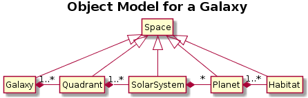
Comments:
- in well-drawn UML there would be only one inheritance triangle
- in coarse-grained classes, omit/hide empty field/method sections
- PlantUML does not always read like English intuition suggests,
vis a vis *-right- syntax
Association Details
There are many details added to associations to show more information about
the relationship. Some of these details are discussed in Chapter 5 in your
text.
- link
- just as classes have instances at runtime called objects, associations have instances at runtime
called links. Links occasionally are so important and complicated that they need
their own attributes. The main information about them is usually their lifetime, and what
instances they are connecting.
- multiplicity
- a.k.a. cardinality, it is the number of object instances per link instance in a given relationship
- qualifier
- some many-to-one relationships have a unique key used to traverse the association.

- roles
- the different ends of an association may have differing roles associated with them.
Especially useful if both ends of an association connect the same class.
- composition
- there is a special kind of aggregation called composition, which denotes aggregations
in which the component parts have no existence apart from the whole thing. The relationship
is hardwired, static, or constant. Composition
is marked using a filled diamond; hollow diamond means a regular (transitory, or dynamic)
aggregation.
Lecture 14
Scroll back a bit and talk about roles and composition.
Big Issues with UML Class Diagrams
- The associations may be lame.
- Give extra thought to them.
- Avoid missing associations.
- Avoid faux aggregation.
- Identify/define user-defined relationships from the app domain.
- The diagram may be ignored or becomes obsolete
- Cowboy coders ignore design entirely
- Change is inevitable
- It is contrary to human nature to keep diagrams up to date
during a coding binge.
- Reverse engineering tools might help.
- class2uml
- UmlGraph+
Graphviz --
not just a reverse engineering tool, but it can be used that way.
Resulting diagrams can be placed in javadocs which is cool.
- doxygraph+
Doxygen
- The mapping of diagram to subsequent code may be unnavigable.
In order to map diagram elements to code elements or vice versa,
you generally have to label elements within one phase, and refer
to those elements by name or number within the other phase. This
is broadly refered to as traceability and can apply across all
phases of software engineering.
Class Diagram Example(s) from the Past
The following past CS383 student homework submission let's us talk about
many good and bad things you can do in your class diagrams.
Things to aspire to:
- have your work peer reviewed
- waste no ink
- primary axis (horizontal or vertical)
- primary association (aggregation or inheritance)
- balance, minimize distance, avoid edge crossings...
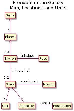
Created by:
@startuml
title Freedom in the Galaxy\nMap, Locations, and Units
hide circles
hide members
class Game {
 }
Game o-- "*" Planet
Planet o-- "1-3" Environ
Environ -- "0-2" Stack : "is located at"
Stack -right- Mission : "is assigned"
Stack o-- "*" Unit
Stack o-- "*" Character
Character -right- "*" Possession : owns
Environ -right- Race : inhabits
But more important than all this:
- focus on your relationships (associations)
- write down (what you understand is) the meaning of those relationships
in a supporting document.
Lecture 15
Midterm Exam
We decided on Wednesday March 9
What is Due Tonight for HW#3
10pm due date for what?
- individual's practice w/ class diagrams
- Group-coordinated assembly of useful class diagrams
- Old/past sprint backlog, results, and artifacts thereof
- Plan for the next sprint (who's doing what)
HW#4
Sprint Planning Meeting
Three parts
- Show your past sprint's backlog, and what you accomplished
- What went well, and what needs improvement
- Develop new sprint's backlog, each team member commits to
one or more items.
Lecture 16
WAR impressions
- Your WAR is to tell me what you did and how it went. You should
be specific.
- "To: Client or Project Manager" can just read "To: Dr. J" or some such
- Your activities planned list does not have to include "attend class";
I do expect that, but it is implicit in every WAR.
- Some teams seemed to think that because class diagrams were the
deliverable, that was all you had to work on last week. Really,
you need to be working off a Backlog task list, and giving me and
your teammates about 9 hours/week, either in meetings or on
task list items or on specific deliverable requirements such as UML
diagrams.
- Some of you still need to figure out how to submit WAR in a direct
"Submission Text", not Comments and not an attached .txt submission.
Ask teammates or submit .pdf or .docx if you can't find the right
button to submit a formatted WAR directly on Blackboard.
Adding Detail to Class Diagrams:
From Requirements to Software Design
We have more examples, and more detailed notation for class diagrams to learn,
but first:
- One of your big picture items right now is to work out the details of
what your project consists of. Application Domain Content.
- A second big issue is to figure out a software design that will deliver
that content.
- To produce a software design, we need more detail. How to get it?
- Asking the customer more questions
- Thinking hard and studying.
- From use case descriptions.
Although we will also be adding more details to our class diagrams, and
seeing more examples, it is also time to learn a new UML diagram type:
Sequence Diagrams.
This UML diagram type:
- illustrates the timing relationships and communications
between objects during a computation.
- can be used to elaborate on use case descriptions, taking the
sequence of steps and working out each step's details.
(coarse grained sequence diagram)
- can show interactions between objects
that are needed for any complex operation, i.e. non-trivial method
whose implementation will involve multiple objects.
Shift in perspective often identifies additional classes and methods.
Sequence diagrams are classically used to show parallel threads or processes
and their communication, but they can certainly depict control flow bouncing
around between objects within a single thread. To create a sequence diagram,
you line up all the involved objects as columns along the x axis, and use
the y axis to depict time (or vice versa).
For coarse-grained sequence diagrams, one way to organize is to use columns
like this:
- First column = actor/object who initiated use case/operation
- 2nd column = boundary object used to initiate
- 3rd column = control object in charge of use case
- <<create>> 3rd from 2nd; additional boundaries from 3rd;
entities probably do not get created except in specific situations
(they are usually "persistent" from some prior use case)
- entity objects get accessed by others, they do not access non-entities
Here is an example from a previous semester's class.
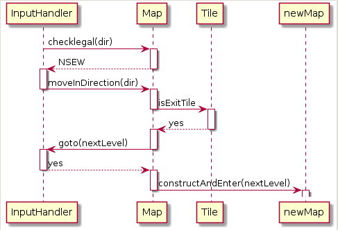
constructed from:
@startuml
hide circle
InputHandler -> Map : checklegal(dir)
activate Map
Map --> InputHandler : NSEW
deactivate Map
activate InputHandler
InputHandler -> Map : moveInDirection(dir)
deactivate InputHandler
activate Map
Map -> Tile : isExitTile
deactivate Map
activate Tile
Tile --> Map : yes
deactivate Tile
activate Map
Map -> InputHandler : goto(nextLevel)
deactivate Map
activate InputHandler
InputHandler --> Map : yes
deactivate InputHandler
activate Map
Map -> newMap : constructAndEnter(nextLevel)
deactivate Map
activate newMap
Lecture 17
Announcements
- Midterm coming up on Wednesday 3/9, right? Review on Monday 3/7.
Sequence Diagrams Resources
Discussion of Sequence Diagrams
Other than: because it is required preparation for a midterm exam,
under what circumstances would you want to do a sequence diagram?
- Look for pieces of functionality where your design has not
broken out things a fine-enough granularity yet.
- Has your team been too conservative in its interpretation of
what some requirements or use cases entail?
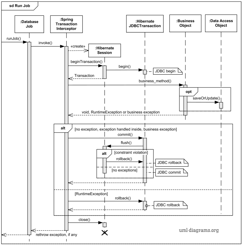
In the following example from c-jump.com, what variations on the
sequence diagram notation do you detect? Are they understandable?
Do they seem like improvements or bugs?
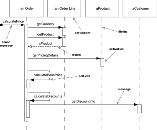
OK, what about the following example from uml-diagrams.org?
User-defined Association Examples
Here is an association you might see in a human resources application:
|
|
employee employer
Works-for
|
|
What are some example instances of this association?
Here is a more detailed version of that association:
| Person | name
SSN
address
salary
job title |
|
employee employer
*
Works-for
|
|
There is a multiplicity, since many people may work for the same company.
But what if a given person works for more than one company?
Here is an association you might need for a geography application:
Now, what are some examples of this association? Give me some instances --
and their "links". To include more information in this association, we need
to know:
- How many capitals can a country have?
- How many countries can a city be capital of?
- Does every country have a capital? Vice-versa?
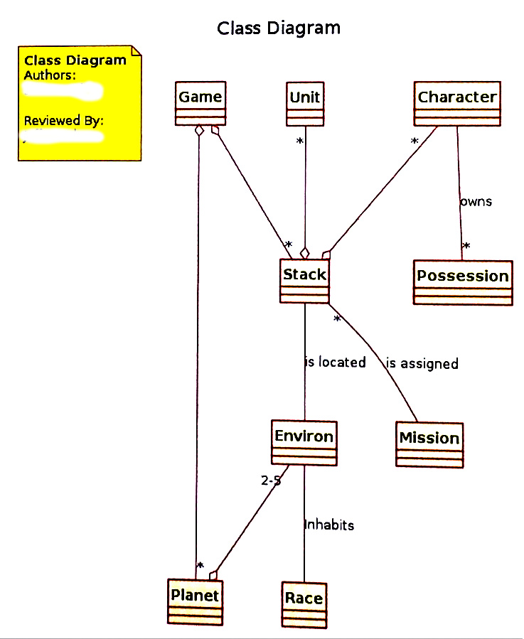
Class Diagrams Examples -- closer to home
As a larger example of class diagrams and associations, consider a previous
semester's project. They produced two, overlapping class diagrams, one
focusing mainly on
cards and card decks
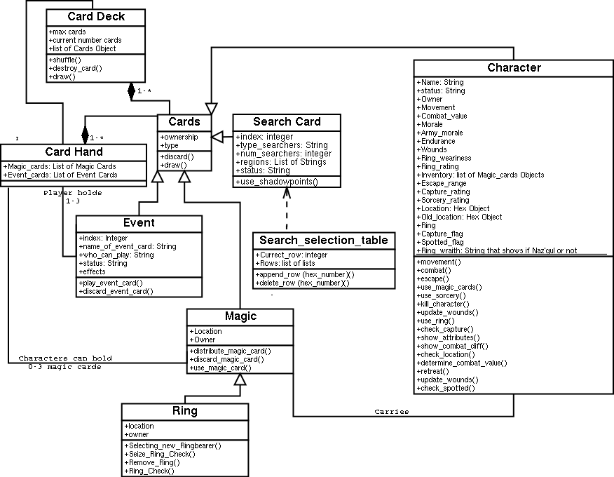
and one focusing on
characters, units, and the map.
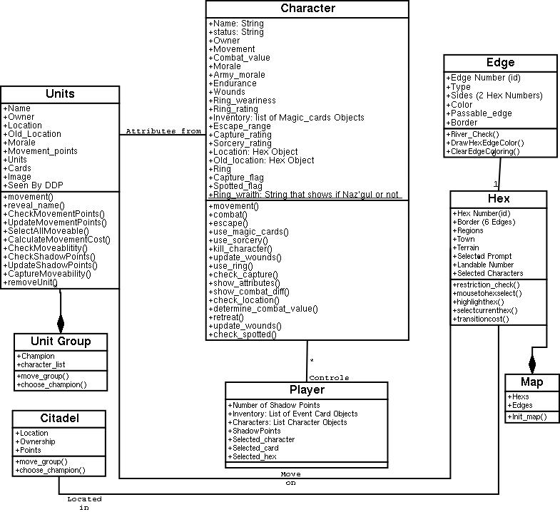
We can look at these two diagrams and
consider what previous students did right, and what needs to be changed.
We can also work, as an example, some of the classes and
relationships for our projects.
A "Good" Class Diagram...
- Has more two classes
- If you only have 1-2 classes, you don't need a diagram.
- Has meaningful associations, adequately defined
- No blank lines. No faux aggregation or inheritance. One or more
sentences of supporting English prose to define classes and user-defined
associations.
- Notationally, triangles, diamonds and so on in the correct locations
- Nothing missing, nothing backwards
- Has an appropriate focus on application domain
- Showable to a customer domain expert, not encumbered with
implementation artifacts such as standard library classes.
- Read:
http://www.agilemodeling.com/artifacts/classDiagram.htm
- Figure 9 towards the end of this article looks fishy to me. Why? How would
you fix it?
Lecture 18
Statecharts
A statechart, or state diagram, depicts dynamic properties of a system.
A statechart consists of
- a set of states
- drawn as circles, ovals, or rectangles, with a usefully semantic
name/label inside.
- a set of transitions
- drawn as arrows from one state to another.
- a start state, and a set of final states
Statecharts are a non-trivial extension of finite automata, because:
- states may have activities associated with entry, exit, a finite task,
or ongoing while in the state.
- instead of "input symbols", transitions have trigger events
and conditions, drawn inside square brackets
- you can have a triggerless transition so long as it either has a
condition, or the state as a (completable) activity
- events may have associated actions
Statechart Diagram Examples
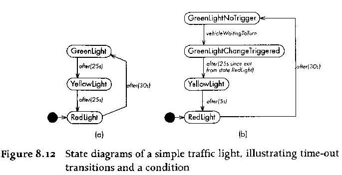
Compare these with the plantuml:
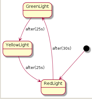
from:
@startuml
GreenLight --> YellowLight : after(25s)
YellowLight --> RedLight : after(25s)
RedLight --> GreenLight : after(30s)
[*] --> RedLight
A "Good" Statechart Example
- Has more than a couple states
- Typically, transitions include cycles, or have enough transition
complexity to warrant a diagram. Not usually a simple linear
sequence or tree.
- Has a meaningful, well-defined scope -- the class(es) whose behavior
it governs are specified
- the representation of the states is
explicit (which fields, and which value ranges, denote the states).
- the transitions are are labeled with events. conditions are present
where needed
- actions, activities, or changing behavior controlled by the states is
given
-
http://www.atmarkit.co.jp/fjava/devs/mda_tool01/statechart.gif
Statechart Example
Before each UML diagram is accepted as part of our software
design, it should be reviewed by a peer for correctness and clarity.
We are just learning statecharts, so for example, what are
your thoughts on this one:
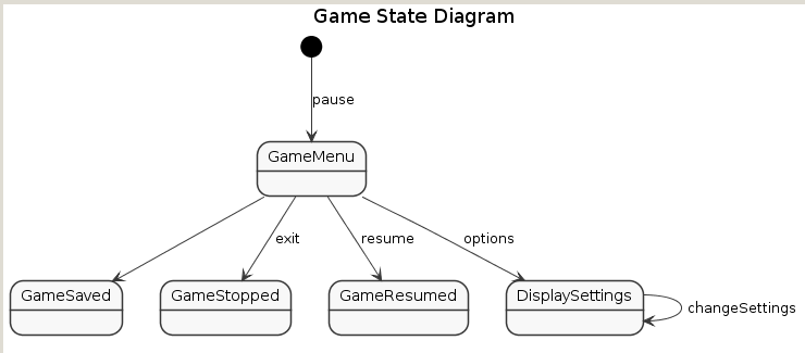
When you are asked to write a statechart on an exam:
- Do not leave any transitions blank. What triggers the transition?
- Do not write a flow chart (UML activity diagram)
- Ask for each state: what happens afterwards? Usually it will
be one or more transitions to other states. Occasionally the
state is a final state and should be marked as such; this is
pretty dramatic, implying object death or some such.
Tieing StateCharts and Class Diagrams together
StateCharts are all about working out details, which may result in
additions and corrections to class diagrams.
- Don't mix multiple UML diagram types in the same figure
- Do provide enough common naming and cross-referencing
so that diagrams relate appropriately.
- For any statechart, the connection to the class/object model does need
to be clear.
- "what class does it govern?"
- What attributes store the states?
- What methods in what classes correspond to events/transitions that
cause state changes.
Consider the following example...
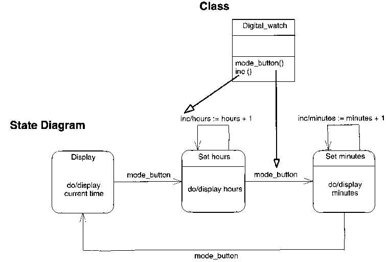
More Statechart Examples
What is good, and what is missing or wrong, in the following examples,
adapted from famous software engineering textbooks?
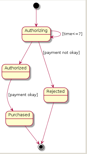
Generated from the following plantuml:
[*] --> Authorizing
Authorizing --> Authorized
Authorizing --> Rejected : [payment not okay]
Authorizing --> Authorizing : [time<=7]
Authorized --> Purchased : [payment okay]
Purchased --> [*]
Rejected --> [*]
Suppose you have a class
| Fuel |
|---|
min_quantity=100
current_quantity |
and you want a statechart to track when fuel needs to be ordered. What would
you have to add to the following statechart in order for it to make sense?
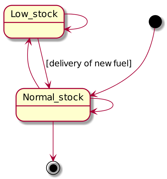
Generated from the plantUML
scale 600 width
[*] -right-> Normal_stock
Normal_stock --> Normal_stock
Normal_stock -left-> Low_stock
Low_stock --> Low_stock
Low_stock --> Normal_stock : [delivery of new fuel]
Normal_stock --> [*]
What is wrong with the following chicanery, adapted from a famous software
engineer's published textbook? It purports to describe behavior within a
class Inventory, whose public API includes methods order_fuel()
and order_part().
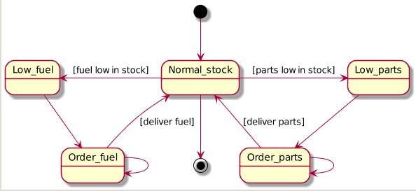
Rendered by the plantuml
scale 600 width
[*] --> Normal_stock
Normal_stock -left-> Low_fuel : [fuel low in stock]
Low_fuel --> Order_fuel
Order_fuel --> Order_fuel
Order_fuel --> Normal_stock : [deliver fuel]
Normal_stock -right-> Low_parts : [parts low in stock]
Low_parts --> Order_parts
Order_parts --> Order_parts
Order_parts --> Normal_stock : [deliver parts]
Normal_stock --> [*]
The following figure shows one author's idea of a statechart for an
online business processing an order.
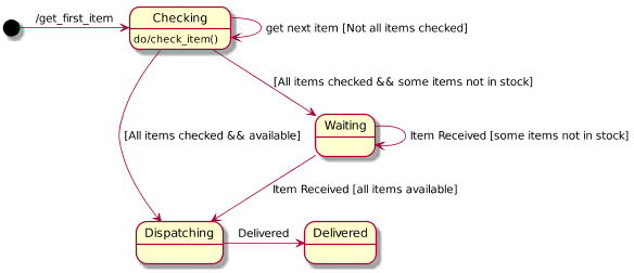
scale 600 width
[*] -right-> Checking : /get_first_item
Checking : do/check_item()
Checking --> Dispatching : [All items checked && available]
Dispatching -right-> Delivered : Delivered
Checking --> Waiting : [All items checked && some items not in stock]
Waiting --> Dispatching : Item Received [all items available]
Waiting --> Waiting : Item Received [some items not in stock]
Checking --> Checking : get next item [Not all items checked]
Lecture 19
Frequently, a statechart will get refined with additional states,
upon closer study of the application domain semantics.
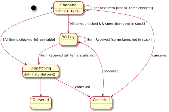
scale 600 width
[*] -right-> Checking
Checking : do/check_item()
Checking --> Dispatching : [All items checked && available]
Dispatching --> Delivered
Dispatching : do/initiate_delivery()
Checking --> Waiting : [All items checked && some items not in stock]
Waiting --> Dispatching : Item Received [all items available]
Waiting --> Waiting : Item Received [some items not in stock]
Waiting --> Cancelled : cancelled
Checking --> Cancelled : cancelled
Dispatching --> Cancelled : cancelled
Checking --> Checking : get next item [Not all items checked]
What do you make of the following statechart, for processing an invoice?
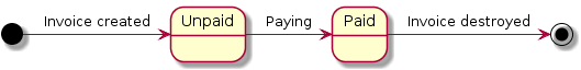
[*] -right-> Unpaid : Invoice created
Unpaid -right-> Paid : Paying
Paid -right-> [*] : Invoice destroyed
How about
the following 5-state statechart? Are there any bugs?
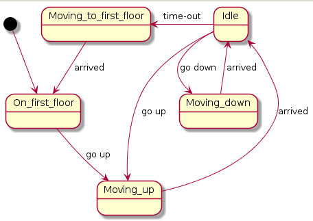
[*] --> On_first_floor
On_first_floor --> Moving_up : go up
Moving_up --> Idle : arrived
Idle -left-> Moving_to_first_floor : time-out
Moving_to_first_floor --> On_first_floor : arrived
Idle --> Moving_down : go down
Moving_down --> Idle : arrived
Idle --> Moving_up : go up
Is the following a refinement/improvement? What has changed?

[*] --> On_first_floor
On_first_floor --> Moving_up : go up(floor)
Moving_up --> Idle : arrived
Moving_up : do/moving_to_floor()
Idle -left-> Moving_to_first_floor : time-out
Moving_to_first_floor --> On_first_floor : arrived
Idle --> Moving_down : go down(floor)
Moving_down --> Idle : arrived
Moving_down : do/moving_to_floor()
Idle --> Moving_up : go up(floor)
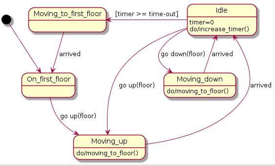
[*] --> On_first_floor
On_first_floor --> Moving_up : go up(floor)
Moving_up --> Idle : arrived
Moving_up : do/moving_to_floor()
Idle -left-> Moving_to_first_floor : [timer >= time-out]
Idle : timer=0\ndo/increase_timer()
Moving_to_first_floor --> On_first_floor : arrived
Idle --> Moving_down : go down(floor)
Moving_down --> Idle : arrived
Moving_down : do/moving_to_floor()
Idle --> Moving_up : go up(floor)
The SSRS
In CS 383 each team shall construct a book documenting their project.
The first major chapter, on requirements, is about finished and will
consist of our master use cases and preliminary class diagrams.
The IEEE has published a standard for requirements specifications documents,
which we call the SSRS, that could be used as a template for this chapter.
- The SSRS template was original developed
by Paul Oman of UI as a Word document for his research teams.
- Are there any major aspects of requirements analysis in the SSRS
that we need and haven't done already? If so, we
should add them to the backlog, along with whatever
software design and implementation tasks are to come.
- Using Git to merge changes works well with
line-oriented, text-based content, so the SSRS template
was rewritten as a LaTeX document for you to use.
- Dr. J eventually decided it should be a chapter
in a 383 book template.
The other source files are:
ssdd.tex,
tpd.tex,
iod.tex,
smd.tex,
did.tex.
- Beware binaries: revision control doesn't cover changes to binary
files such as image files. This is the single biggest argument for
using a textual UML tool such as plantUML or MetaUML
instead of a neato UML drawing tool like Dia.
Overview of Projects
Software engineering applies to small projects, but matters more for
big projects.
- Dividing the Labor
- Scheduling delivery of various parts of the system
- Where Does the Buck Stop?
- How do we document bugs?
- How do we evaluate the system?
- How are requirements to be documented?
- Who talks to the client?
Project Communications
Plan to try out and/or gain experience with each of these forms of
communication this semester.
- Problem Inspection - gather information about the problem
- did first pass, reiterate as needed
- Requests for clarification
- you may start asking me questions any time now.
- Status meetings
- in particular, we will do a form of "sprints" as defined by
agile methods/extreme programming
- Peer reviews
- aside from pair programming, which is peer review as code is written,
there are reviews of design work and/or code that you conduct within
your team or subteam.
- Client / Project Reviews
- you learn a lot when reality intrudes on your wishful thinking
- Releases
- software releases are the ultimate awesomest form of communication
- Requests for change
- Early software engineers blamed all their troubles on the customer.
Agile software engineers embrace requests for change, and provide the
customer with functionality as early as possible so that they get this
feedback right away.
- Issue resolution
- Testing, bug reports, managing bugs and getting them fixed in a timely
manner all contribute to the overall success or failure of a project.
Team Organization
With, say, 9-15 people on your team, you will probably divide
labor and organize into subteams. Within the subteam, different team members
may play (potentially multiple) varying roles: programmer, graphic artist,
user interface designer, system architect, network programmer, website-
and user-manual author, etc.
Question:
how do (sub)teams talk to other (sub)teams?
| Hierarchy | Peer-based | liaison-based
|
|---|
| Each subteam has a leader. Leaders of each subteam meet regularly.
Pro: scalability. Con: leader spends much of their time in meetings.
| Anyone talks to anyone.
Pro: politically correct, egalitarian, fits student mind-set.
Con: chaotic. hard to find the right person to talk to.
| Subteams have a designated liaison that other teams may contact.
Pro: offloads communication from overworked leaders.
Con: liaison potentially adds another layer of indirection to
communication. Layers slow things.
|
Schedule
This is harder than just developing a linear sequence: in a large team
effort, multiple things must be developed in parallel, and various tasks
cannot be started until others are completed. Gantt and PERT charts
are two ways to present this information, one with a strong horizontal
time axis, and one without.
Lecture 20
Midterm Review
Check out this extended sample of questions from past midterms. The midterm will
not be this long; this appears to be two or more exams' worth:
lecture #21 started here
Where we are at
- > halfway through the semester, 7 weeks left
- a long way to go on your projects
- behind on lectures; need to finish
up on software design and talk about implementation
- then talk about testing, metrics.
- need to give all of you some practice talking about your software
engineering work. Considering between rotating sprint report duties,
vs. big hairy end-of-semester presentations.
Software Project Estimation
Logically it seems you would
want to estimate things near the start of a project, like after you
have sized it up via requirements analysis.
I looked at websites for some of this material, in addition to consulting
Roger S. Pressman's book on software engineering.
-
Historically, software was an insignificant % of the budget for a
computer project. Moore's law has fixed that.
- Big software cost estimate errors kill corporations, and someday countries.
- Ways to be accurate: estimate after finished, estimate base done having
done the same thing previously, decompose into estimatable subcomponents,
use an (empirically validated?) model
- Estimate based on size, in LOC or function points (FP)?
- The reason decomposing helps: "similar" projects are rare, but similar
functions, classes, modules, data structures and algorithms are common
- Example based on LOC: after careful decomposition, one gets an estimate
that a software will take 33KLOC, that the organization writes 620LOC
per person-month, and each month costs $8K. Then total cost is $431K
and 54 months. (Pressman)
- Example based on FP: after careful decomposition, the project has
320 FP, but weighted by difficulty it is adjusted to 375 FP. The
organization averages 6.5 FP/month @ $8K, cost/FP is $1230 and
total project cost is $461K and 58 months. (Pressman)
Boehm's COnstructive COst MOdel.
Barry Boehm is one of the luminary founding
fathers of software engineering, inventor of the spiral model of
software development, and one of the early predictors that software
costs would come to dwarf hardware costs in large computer systems.
COCOMO is acronym-laden, and subject to perpetual tweaking and twisting of its
interpretation. Whatever I give in lecture notes about it will contradict
various COCOMO authoritative sources.
COCOMO starts from an estimate of SLOC (source lines of code). This includes declarations, but
no comments, no generated code, no test drivers). Boehm also refers
to KDSI (thousands of delivered source instructions) and it appears to
be used more or less interchangeably with SLOC.
Scale Drivers
COCOMO specifies 5 scale drivers. They are rated from
"very low" to "extra high". These are like exponents;
a bad enough scale driver will severely affect your
ability to develop larger-scale projects.
- precedentedness
- has it been done before? have we done it before?
- development flexibility
- are programmers free to use the best tools for the job? or constrained?
- architecture / risk resolution
- how thorough, and how reviewed, is the design? incompletness == risk.
- team cohesion
- do we get along? ranges from "very difficult interactions" to
"seamless interactions". Not just developer team: stakeholders
- process maturity
- measured using the Capability Maturity Model
Cost Drivers
COCOMO has ~15-17 cost driver parameters that assess not just the software to be
developed, they assess your environment and team as well. They are
rated one of: (very low, low, nominal, high, very high, extra high),
with the different values contributing multipliers that combine to
form an effort adjustment factor. From
Wikipedia:
| Cost Drivers |
Ratings |
| Very Low |
Low |
Nominal |
High |
Very High |
Extra High |
| Product attributes |
| Required software reliability |
0.75 |
0.88 |
1.00 |
1.15 |
1.40 |
|
| Size of application database |
|
0.94 |
1.00 |
1.08 |
1.16 |
|
| Complexity of the product |
0.70 |
0.85 |
1.00 |
1.15 |
1.30 |
1.65 |
| Hardware attributes |
| Run-time performance constraints |
|
|
1.00 |
1.11 |
1.30 |
1.66 |
| Memory constraints |
|
|
1.00 |
1.06 |
1.21 |
1.56 |
| Volatility of the virtual machine environment |
|
0.87 |
1.00 |
1.15 |
1.30 |
|
| Required turnabout time |
|
0.87 |
1.00 |
1.07 |
1.15 |
|
| Personnel attributes |
| Analyst capability |
1.46 |
1.19 |
1.00 |
0.86 |
0.71 |
|
| Applications experience |
1.29 |
1.13 |
1.00 |
0.91 |
0.82 |
|
| Software engineer capability |
1.42 |
1.17 |
1.00 |
0.86 |
0.70 |
|
| Virtual machine experience |
1.21 |
1.10 |
1.00 |
0.90 |
|
|
| Programming language experience |
1.14 |
1.07 |
1.00 |
0.95 |
|
|
| Project attributes |
| Use of software tools |
1.24 |
1.10 |
1.00 |
0.91 |
0.82 |
|
| Application of software engineering methods |
1.24 |
1.10 |
1.00 |
0.91 |
0.83 |
|
| Required development schedule |
1.23 |
1.08 |
1.00 |
1.04 |
1.10 |
|
COCOMO equations 1 and 2
Effort = 2.94 * EAF * (KSLOC)E
Time_to_develop = 2.5(Effort)0.38
where EAF is an Effort Adjustment Factor derived from cost drivers,
and E is an exponent derived from the 5 scale drivers. EAF defaults
to 1 and E defaults to 1.0997. But since these are parameters, it is
largely the structure of the equation that matters. Effort is in
"man-months" or "person-months". Total time to develop is derived
from this number. The co-efficients in these equations are samples
that get adjusted in particular environments.
Example: Average? 8KSLOC?
Then effort = 2.94 * (1.0) * (8)1.0997 = 28.9 person-months
Calculators:
Estimating SLOC
Basic ideas summarized: you can estimate SLOC from a detailed design, by
estimating lines per method for each class, and summing. Or you can do it
(possibly earlier in your project from use case descriptions) by calculating
your "function points" and estimating lines-per-function-point in your
implementation language.
Highlights from the Rubin Scrum Book
Requirements and User Stories
- Detail your requirements just-in-time and just-enough-to-build
- Requirements get progressively refined on demand over a period of time.
- Different requirements will end up requiring different levels of detail
- User stories (card, conversation, confirmation) describe the business
value of each backlog item (some evolve into use case descriptions)
- "As a __________ (user role) I want ___________ (goal) so that ____________ (benefit)."
- Story granularities: epic, feature, story
- INVEST: independent, negotiable, valuable, estimatable, small, testable
- Knowledge acquisition stories versus gathering stories
Product Backlog
- feature, change, defect, technical improvement, or knowledge acquisition
- DEEP: detailed appropriately, emergent, estimated, prioritized
- size estimates in "story points" or "ideal days"
- grooming: creating/refining, estimating, and prioritizing
- up to 10% of sprint time spent on grooming, led by product owner
- backlog items are "ready" to sprint when:
- enough detail is known to estimate it as competable
- dependencies are completed
- sufficient team members have committed
- acceptance and performance criteria; item is testable
- team agrees on how to demo item at next sprint report
lecture #22 started here
Estimation and Velocity
- estimates should be made by the people who will do the work
- product owner describes the work, answers questions
- scrum master coaches and facilitates
- people are better at relative estimates than absolute ones
- product size * velocity = time & money until release
- story points == arbitrary scale, useful for relative comparisons
- ideal hours (or days): hypothetical generic software engineers' time
- Rules of planning poker:
- product owner selects backlog item, reads it
- team discusses item, asks owner questions
- estimators privately select estimate cards
- private estimates simultaneously exposed
- if same, we have an estimate
- if not same, discuss. high and low estimators give reasons
- goto step 3
- velocity == work completed per sprint
Technical Debt
- design and code that works, but is weak. if you don't fix it you suffer.
- Example: creating software fast to get feedback is a good thing...
- the design and implementation had better evolve as
understanding improves, or the initial version hinders later development
- More sample causes: shortcuts, bad design, lingering defects,
poor test coverage, poor release management, lack of platform experience
(e.g. doing Java when you don't know Java)
- at least three kinds: naive, unavoidable, strategic...
- naive debt: bad design or code due to bad/inexperienced developers or
processes.
- unavoidable debt: changing requirements or improved understanding
of the application domain.
- strategic debt: you deliberately do something suboptimal in order to
gain some tactical short-term benefits
- consequences: tipping point, slowdowns, bugs and maintenance costs,
atrophy, underperformance, frustration
- managing: minimize accrual, make it visible, pay it down
- Boy Scout rule: service debt when you run into it
- Financier's rules: repay debt incrementally, highest interest first
Checkout a Few More Agile Methods and Practices
There is more to "agile" than sprints and scrums. Learn the following 4
buzzwords, so you can use them casually in conversation with colleagues, job
interviewers, examinations, etc.
Introduction to System Design
The line between analysis and design is a gray one.
Broadly, requirements analysis was supposed to focus on what the software
should do, while design should figure out how to do it.
In our project, we are still figuring out our requirements, but we need
to work out a design. The best we can do is: resolve any conflicts in
currently-proposed requirements, make any pending decisions, document
what we've identified and agreed on at this point, and call that our
requirements document, realizing that it may have fatal flaws of omission
or commission.
Our next job is to identify design goals, establish an
initial subsystem decomposition, and refine that subsystem decomposition
until all design goals are satisfied [Bruegge].
Design Goals
Some design goals
come from the nonfunctional requirements, and some emerge from further
discussion with the client, and that they all need to be written down.
The nonfunctional requirements are already written down. The client is
not a software designer, what do they know about it? We need to think
"outside the text" a minute here.
Subsystem Decomposition
What exactly is a subsystem? The amount of work a single developer or team
can produce? This idea due to [Bruegge] seems bad on the face of it. The
subsystems should address relatively separable or independent elements
within the overall system; it should be logically driven by the requirements
or our ideas of how to meet those requirements. But it is
the case that one of the consequences of subsystem decomposition is to
identify pieces that persons or teams can focus on in detail.
A subsystem is characterized by what services or interfaces it provides
to the rest of the application.
Object Oriented Design: Adding Detail
You can view object oriented design as a process of adding detail to
class diagrams. We will look at as many examples of this process as we can.
For detailed design, we need to reorganize/regroup and assign teams to
go into the details of various aspects of content delivery and
activities.
User Interface Design
By the next round of turnin, we will need to establish a fairly complete
user interface design for things like the main screen. User Interface
Design is the subject of an entire course and for our purposes
we will have to settle for a rudimentary and primitive introduction.
User interface design starts from what tasks/activities the application
is to support. You probably will discover a few tasks in this phase that
requires a dialog for a task we haven't identified previously. But mainly
we need to design dialogs and sequences of actions to perform specific tasks
in use cases.
Aspects of User Interfaces
- look
- this is the most obvious part of user interface design, but not the
most important part
- feel
- this is like: what clicks perform what operations. how many clicks
does it take. does it feel like you are directly manipulating the
objects on the screen, or does it feel like you are following a long
sequence of orders you receive from the program.
- metaphors
- users can quickly learn an unfamiliar task, or quickly interpret
an unfamiliar graphic, if a familiar metaphor
is used. Examples: "desktop metaphor"
- mental model
- a user interface provides the user with a particular mental model
of how they view the system. designing that model will determine
many aspects of the user interface (what info to show, what tasks
to support)
- navigation rules
- navigation through large structures which don't all fit on the screen
is a central issue for many (most) applications.
A few Obvious User Interface Tips
- Minimize # of clicks for common tasks
- Provide all the information that's needed on a single screen
- Strive for "direct manipulation"
- Modeless is usually better than modal
- Be familiar and consistent with other applications
Design Buzzwords and Vague Concepts
Here are some buzzwords and ideas that relate to design:
Design methods
- 1. modular decomposition
- top-down breaking up function into parts
- 2. data-oriented decomposition
- top-down breaking up information into parts
- 3. event-oriented decomposition
- identifying what changes are to be made, and when they occur
- 4. outside-in design
- blackbox I/O orientation
- 5. object-oriented design
- relationships between data
Things that get designed
- 1. Architecture
- interaction between programs and their environment, including other programs
- 2. Code
- algorithms and data structures, starting with equations, pseudocode, etc.
- 3. Executable/package
- how is this system going to be installed and run on user machines?
"Good" Design
- Low coupling
- Coupling refers to the interdependences between components.
Components need to be as independent as possible.
The book defines many kinds of coupling, including content coupling,
control coupling, stamp coupling, and data coupling.
- High cohesion
- Cohesion refers to the degree to which a component is focused
and connected internally (it is almost "internal coupling").
Bad cohesion has a single component doing unrelated tasks.
Bad cohesion may coinside with lots of duplicate code (same
thing repeated with slight changes for different tasks).
The book defines levels of cohesion: coincidental, logical,
temporal, procedural, communicational, sequential, functional.
- Minimal complexity
- There are several types of complexity, but in general, complexity
is bad, and the goal is to minimize it while meeting requirements.
Most of the complexity measures that are out there measure the
complexity of code, but we are talking about design right now.
Designs that are complex, or designs that poorly address the
application domain and requirements, lead to complex code.
Bad programmers can of course create complex code from even good designs.
Examples
Design Patterns
Reading Assignment:
Design Patterns Background
Design Patterns were invented in homage to architectural patterns,
specifically the work of Christopher Alexander. Their initial introduction
for software design, in a book by Gamma, Helm, Johnson and Vlissides in 1995,
had an electrifying effect: suddenly it was no longer possible to talk about
software design without referring to as many of the patterns as possible.
A whole mini-industry and cult sprang up around the task of specifying as
many patterns as possible. Of course, most of those patterns are not
very useful.
The original design patterns book described in detail 23 reoccurring
patterns in software, divided into three main categories: creational
(5 patterns),
structural (7 patterns), and behavioral (11 patterns).
Each pattern is described exceedingly well in
prose and outlined in a UML class diagram, after which example
implementations are sketched in C++ or Smalltalk. Within all three
categories a great deal of similarity can be observed, such as the heavy
use of abstract classes; enough to suggest the existence of meta-patterns.
At least one software engineering textbook author (Bruegge, section 8.4.7) has
suggested a sort of buzzword-based "expert system"
for detecting when natural language requirements or design prose suggests
particular design patterns, for example when you hear something like
"policy and mechanism should be decoupled", a light dings in your head
and you say "this sounds like a job for.... a Strategy!"
The design patterns fad has died down, but the concept of design patterns
has been thoroughly institutionalized by the software engineering community.
What is a Design Pattern?
Minimalist Definition
A quad-tuple consisting of:
a pattern name
a description of what problem it solves
a description of the solution
an assessment of consequences and implications of the pattern
Expanded Definition
Name and Classification
Intent
Also Known As
Motivation
Applicability
Structure (e.g. UML)
Participants
Collaborations
Consequences
Implementation
Sample Code
Known Uses
Related Patterns
lecture #23 started here
How Design Patterns Solve Design Problems
finding objects - if the pattern says you need one, you need one
determining granularity - several patterns address granularity explicitly
specifying interfaces - patterns describe part or all of the
public interfaces of the classes in them
specifying implementations - patterns may include known-efficient
code samples
code reuse - "design reuse facilitates code reuse"
How to Select a Design Pattern
GoF suggest several ways, such as
look for which design problem above affects you, then look for
design patterns that pertain to it
scan all the patterns' Intent sections
study how patterns interrelate
study patterns of similar purpose - to tell when to use which
I would just add that, first you familiarize yourself with a bunch
of design patterns, and then when doing design you recognize which
pattern to use via deja vu.
How to Use Design Patterns
Buy the GoF book, read the pattern in detail
Look at the sample code to get a concrete feel for it
Apply (translate) the pattern Structure section to your application classes Adapt the sample code when it is appropriate to do so; otherwise write your own
Some Cynical Observations About Design Patterns
Of course these were not new inventions, they were a catalog of
tried and true methods. That is OK.
Design Patterns proponents are trying to create a common vocabulary of
buzzwords, to reduce the cost of communication and increase the level
of understanding when software engineers are talking with one another.
The Patterns
We will not cover all of the GoF design patterns, several are similar
to each other and they are not all equally important.
A ton of the examples in the Design Patterns book revolve around the GUI
aspects of "a diagram drawing tool" (uniquely relevant for some
instances of CS 383, such as Fall08)
Composite
Compose objects into tree structures to represent part-whole hierarchies
(i.e. aggregation), plus:
-
Treat individuals and composites uniformly.
- The client won't have to know
whether they are working with a leaf or not.
- New kinds of leaves won't require that the hierarchy code be modified.
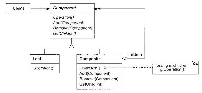
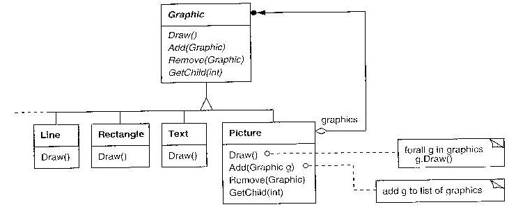
Abstract Factory
Provide an interface for creating objects without specifying their
concrete classes.
Example: a UI Toolkit that can create either Qt or Windows-native components.
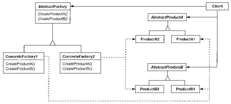
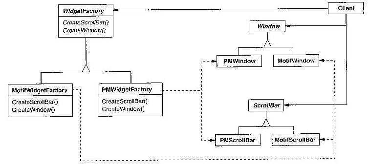
Builder
Separate the construction of a complex object (traversal
algorithm) from its representation (data structure),
so that the same construction process can create different representations.
Example: an RTF reader might parse input (construction process), producing
different representations for different output (ASCII, LaTeX, Wysiwig...)
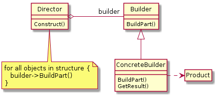
From the following plantUML:
hide empty members
hide circle
Director o-right- "builder" Builder
Director : Construct()
note bottom of Director : for all objects in structure {\n   builder->BuildPart()\n}
Builder <|-- ConcreteBuilder
Builder : BuildPart()
ConcreteBuilder : BuildPart()
ConcreteBuilder : GetResult()
ConcreteBuilder .right.> Product
Instantiation of the above pattern:
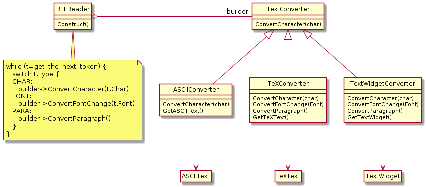
hide empty members
hide circle
RTFReader o-right- "builder" TextConverter
RTFReader : Construct()
note bottom of RTFReader : while (t=get_the_next_token) {\n   switch t.Type {\n   CHAR:\n      builder->ConvertCharacter(t.Char)\n   FONT:\n      builder->ConvertFontChange(t.Font)\n   PARA:\n      builder->ConvertParagraph()\n   }\n}
TextConverter <|-- ASCIIConverter
TextConverter : ConvertCharacter(char)
ASCIIConverter : ConvertCharacter(char)
ASCIIConverter : GetASCIIText()
ASCIIConverter ..> ASCIIText
TextConverter <|-- TeXConverter
TeXConverter : ConvertCharacter(char)
TeXConverter : ConvertFontChange(Font)
TeXConverter : ConvertParagraph()
TeXConverter : GetTeXText()
TeXConverter ..> TeXText
TextConverter <|-- TextWidgetConverter
TextWidgetConverter : ConvertCharacter(char)
TextWidgetConverter : ConvertFontChange(Font)
TextWidgetConverter : ConvertParagraph()
TextWidgetConverter : GetTextWidget()
TextWidgetConverter ..> TextWidget
Factory Method
Let subclasses decide which class to instantiate for a specified
object-creation interface.
Example: application framework needs to instantiate classes, but
only knows about abstract classes, which it cannot instantiate
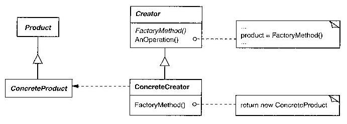
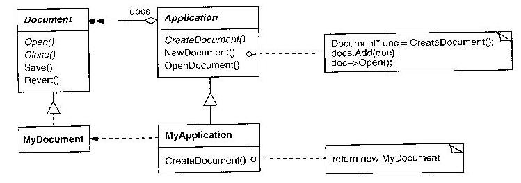
Prototype
Specify objects to create using a prototypical instance; create objects
by copying.
Example:
Toolbar-based applications where you create an instance by clicking on one.
The toolbar may be generic framework code. Each button could be a different
subclass, but instead attach a different prototype instance to each one.
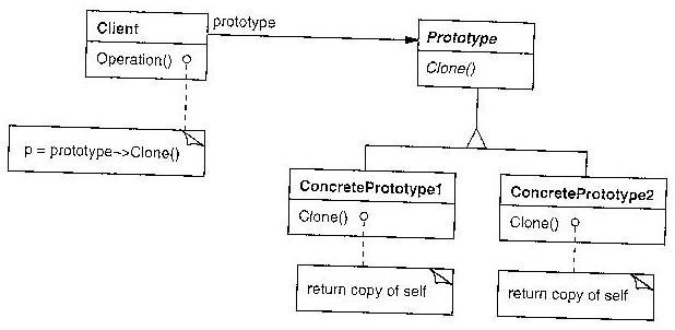
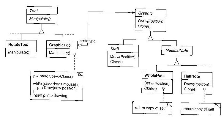
Singleton
Ensure a class has only one instance, and provide a global point of access.
Example: a print spooler. Highlander quote: "There can be only one".
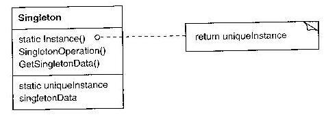
Adapter
Convert the interface of a class into another interface, expected by clients.
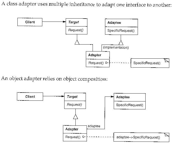
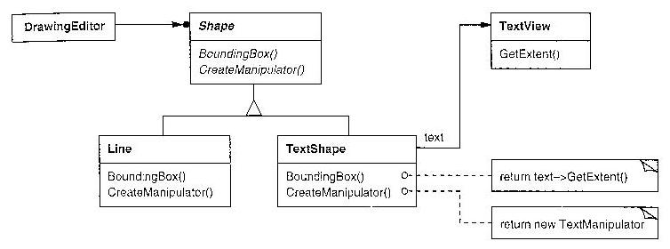
Bridge
Decouple abstraction from implementation, so the two can vary independently.
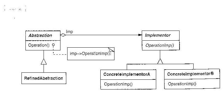
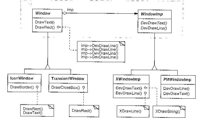
Design Patterns - Dr. J's "Personal Favorites"
These patterns seem valuable in Real Life, from my personal experience.
Decorator
Attach additional responsibilities to an object dynamically.
An alternative to subclassing for extending functionality.
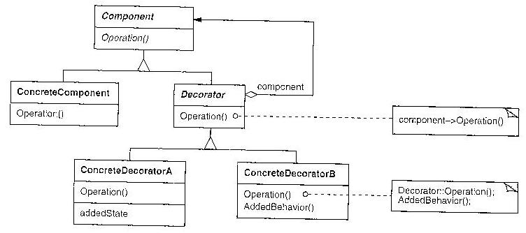
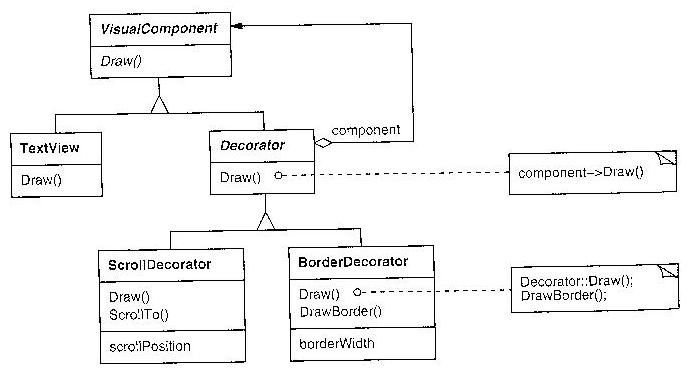
Facade
Provide a single unified interface to a set of subsystem interfaces.
Goal: reduce coupling between a subsystem and the rest of the system.
Can anyone say "DirectX" or "SDL"?
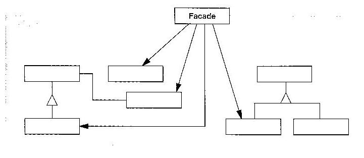
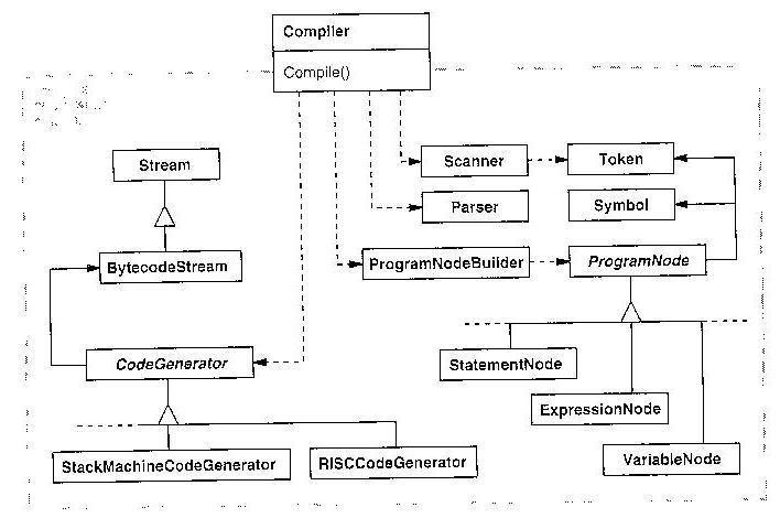
Flyweight
Use sharing to support large numbers of fine-grained objects efficiently.
Share the constant part in a big pool; reduce the cost of
thousands-of-similar-objects. GoF mentions word processor
example, but Dr. J has lots of personal examples from
the field of compilers.
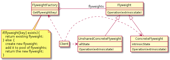
from the plantuml:
hide circle
hide empty members
FlyweightFactory o-right- "flyweights" Flyweight
FlyweightFactory : GetFlyweight(key)
note bottom of FlyweightFactory : if(flyweight[key] exists){\n   return existing flyweight;\n} else {\n   create new flyweight;\n   add it to pool of flyweights;\n   return the new flyweight;\n}
Client .up.> FlyweightFactory
Flyweight <|-- ConcreteFlyweight
Flyweight <|-- UnsharedConcreteFlyweight
Flyweight : Operation(extrinsicstate)
ConcreteFlyweight : Operation(extrinsicstate)
ConcreteFlyweight : intrinsicState
UnsharedConcreteFlyweight : Operation(extrinsicstate)
UnsharedConcreteFlyweight : allState
Client .right.> ConcreteFlyweight
Client .right.> UnsharedConcreteFlyweight
Flyweight -- key properties
Use flyweight pattern when
- You have large number of objects
- The objects have substantial shareable constant state ("substantial"
means: a lot more than a pointer's worth)
What you are really doing: pooling the constant part, thus shrinking the
non-shared part. Design patterns literature will often refer to the dynamic
part of the instance as the extrinsic part, and the pooled/shared part as the
intrinsic part. Extrinsic part might be represented by a (smaller) instance
OR by the client code, which passes it in as parameter(s) to the (shared)
flyweight instance when requesting its behavior.
"Smoking Gun" Flyweight Examples
Personal explerience and googling "flyweight examples" turned up many
examples.
- word processor
- the design patterns book mentions that much of the elements of a
rich text document can be shared. Not just repeated string text,
but the font information, etc.
- lexical analysis
- similar to the word processor example, compilers can often share
memory for repeated elements in their data structures. Not just
the string identifiers (which repeat a lot) and constants, but other
lexical attributes (such as what filename the token was found in).
Shareable structures also occur in syntax, type checking subsystems, etc.
- phone systems
- things like "ring tone generators" can be shared
across a large number of telephone users
- insect populations
- I guess these are knee-jerk examples for a pattern named after an insect...
- war games
- many games (and movie animation softwares) have to simulate a large
number of solders. Although part of their data is instance-specific
(location and orientation, health and ammo), another very large part
of their data (3D model of physical appearance) is shareable
Proxy
A placeholder for another object to control (and provide) access to it.
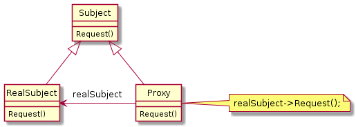
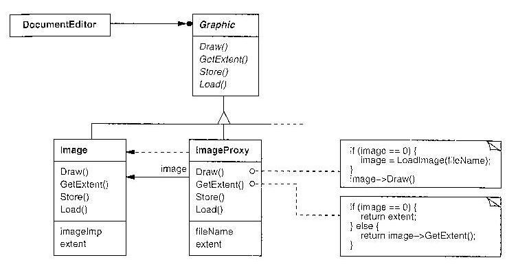
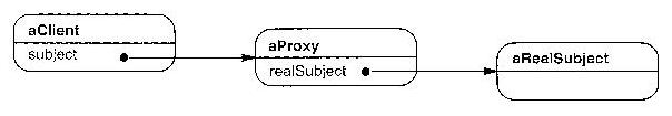
"Smoking Gun" Proxy Examples
- "Secure" objects
- Proxy might be in place in order to impose a layer of security on access
- Distributed object
- Local object may be serving as a proxy for a remote object.
- Thread-local and process-local proxy
- Variations on "distributed object": any situation where an
object's access is less than direct and you want to improve ease of use
- Reference counting or other instrumentation
- Provide a proxy for a pointer and you can count # of references to it.
Or attach other monitoring capabilities, without modifying the
object being monitored. Similar to a decorator, isn't it?
Chain of responsibility
Give more than one object a chance to handle an incoming message.
Pass the request along the chain until an object handles it.
Decouple the sending of a message from who will receive it.
Fundamental to concepts such as exception handling, and
event-driven programming. Often called delegation.
Note the close relationship here to Composite (chains usually follow
a path from a leaf to a root through a hierarchy), and to the classic
"Chain of Command" used in the military and other hierarchies.
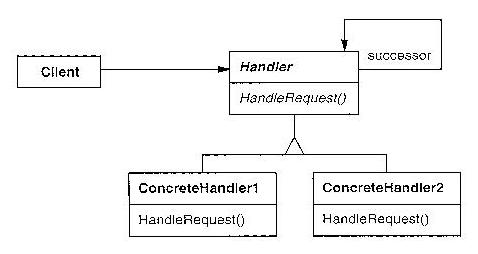
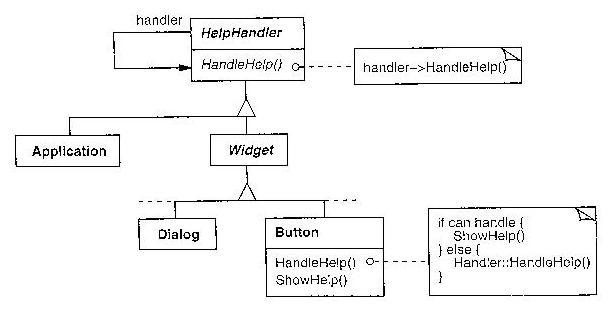
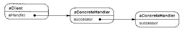
"Smoking Gun" Chain of Responsibility Examples
- in GUI's
- incoming user / gui events are routed through a chain of GUI components
from the outermost window/dialog through intermediate panels into the
inner components, until you find the (first) component that agrees to
handle the event.
- obtaining approvals, lodging complaints
- approvals and complaints often follow a protocol from local to global
- symbol tables in nested scopes
- especially in heavily nested situations, such as pascal programs,
or "big Java" apps with packages inside packages inside packages
Command
Encapsulate a request as an object. Assists with queing the tasks
for later execution, prioritizing them, and supporting an "undo" operation.
Multiple benefits such as queueing and logging.
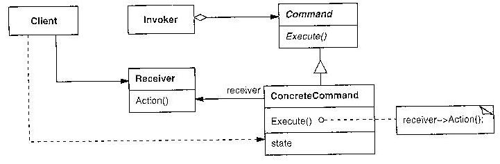
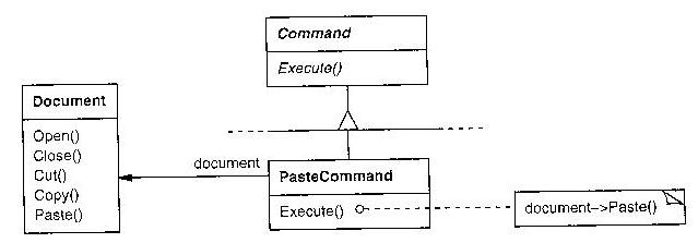
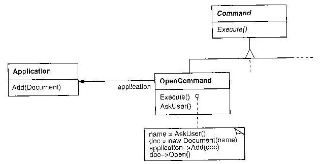
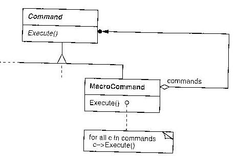
"Smoking Gun" Command Examples
- Thread pools
- If a set of N threads is being shared by many concurrent jobs,
it sure helps for each incoming job to be turned into an object
so it can be placed on a queue.
- Network protocols
- The X11 protocol and many others are structured around the notion
that network messages are serialized commands.
- GUI "Wizards"
- A multi-page GUI wizard can be viewed as constructing (filling in) a
command object which is finally passed on to the rest of the system
when the final page Submit button is pressed.
Interpreter
Interpret sentences in a language by defining and operating on an
internal data structure representation of that language.
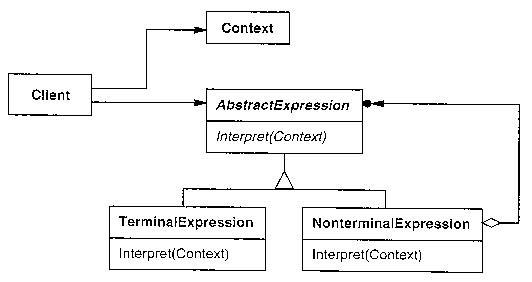
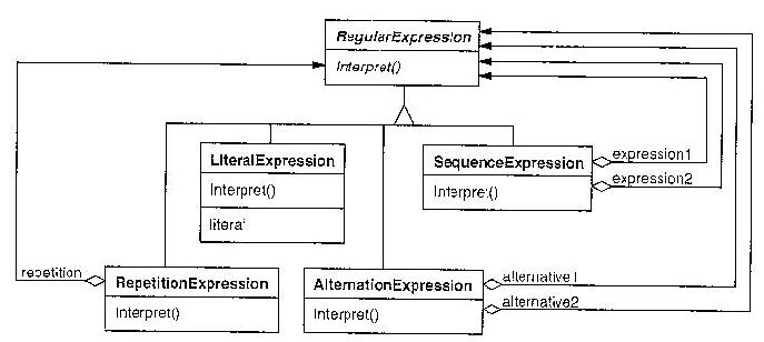
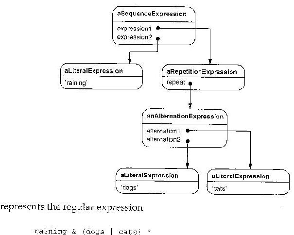
Iterator
Provide a way to access the elements of an aggregate object sequentially.
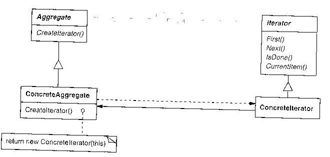
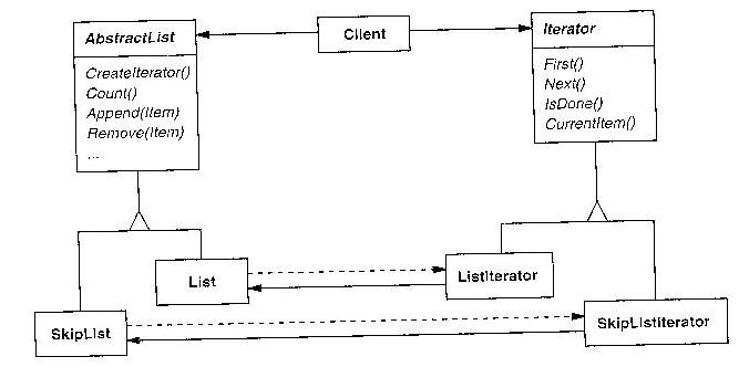
This pattern is too widespread to need much in the way of a smoking gun.
Lots and lots of computing gets done by building collections of things and
walking through them afterwards. It is common to need to support multiple
iteratings on the same collection at the same time, which is what this
pattern achieves, by pulling the "walking through" state out into a separate
object from the collection being iterated through.
Mediator
Define an object that encapsulates how a set of objects interact.
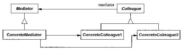
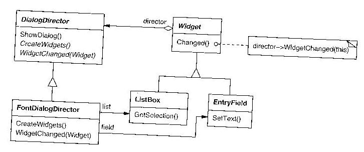
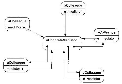
"Smoking Gun" Mediator Examples
- mapping between users and groups in file systems permissions
- As argued on sourcemaking.com, a mediator can be used as an object that instantiates and
manages a many-to-many relationship.
- dialog class in a GUI
- a dialog facilitates interaction between other GUI controls. Does this imply that
mediators might be common in "control" situations in general?
- chat application
- the central server that connects n users is often a mediator.
Memento
Capture and externalize an object's internal state so that the object
can be restored to this state later.
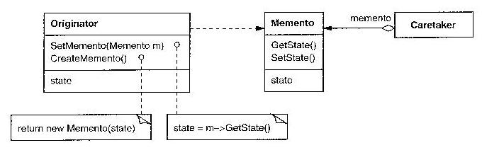
"Smoking Gun" Memento Examples
- Core dumps and other process "restore" and "checkpointing" features
- A traditional mechanism for computer jobs that ran so long that the
odds were good that a machine crash would occur before the job finished.
- Object serialization mechanisms
- These can be used to save on disk OR to move an object to another machine
Observer*
Create a mechanism such that when one object changes its state, all
its dependent observers are notified and updated. Also called "Listeners"
in some systems; a whole "publish-subscribe" paradigm follows this pattern.
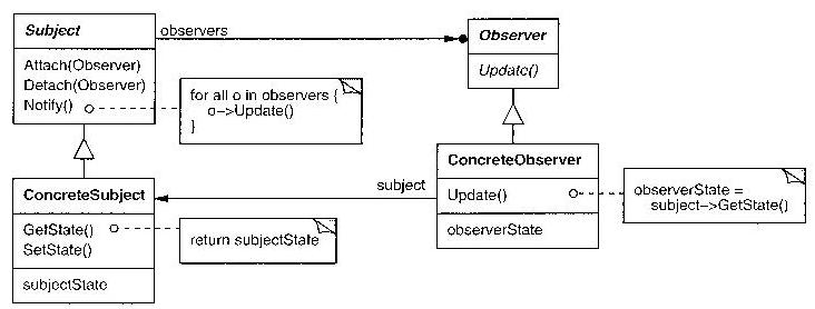
"Smoking Gun" Observer Examples
- the Model-View-Controller
- uses an observer to update the views whenever the model changes
- ...
State
Allow an object to alter its behavior when its internal state changes,
appearing to have changed its class.
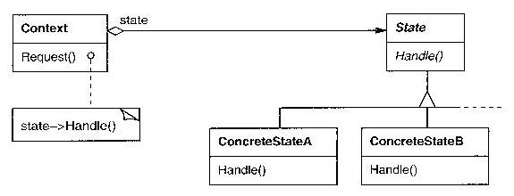
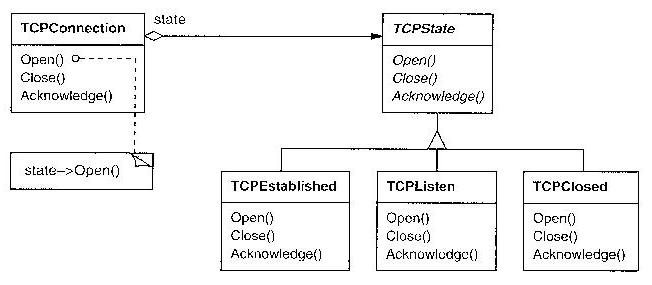
"Smoking Gun" State Examples
- car transmissions, vending machines, ceiling fans...
- essentially, all statecharts??
- "mode-based" user interfaces
- e.g. vi's "insert mode" vs. "command mode"
Strategy*
Define a set of encapsulated, interchangeable, algorithms; allow algorithms
to vary independently of their clients.
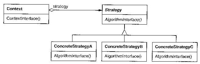
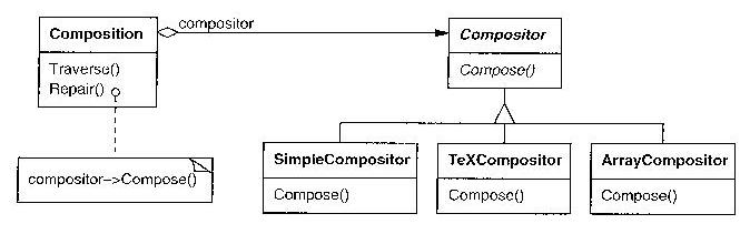
"Smoking Gun" Strategy Examples
- file handling
- for small files, use strategy A, for large files use strategy B
- salaried vs. hourly employees
- methods for calculating their pay will be different
Template Method
Define the skeleton of an algorithm, deferring some steps to subclasses.
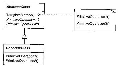

There is no smoking gun needed for the template method, it is a common
way (popularized with direct support in Ada (generics) and C++ (templates))
to share an algorithm across a diverse range of data types.
Visitor
Represent an operation on elements of an object structure; enable new
operations without changing the element classes.
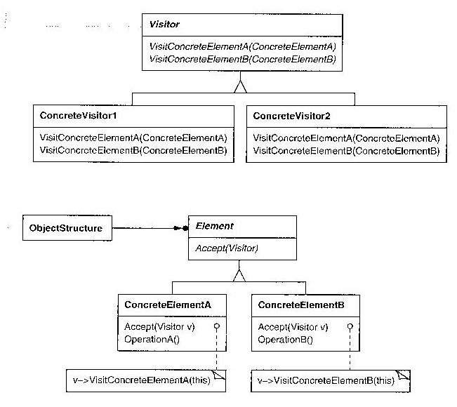
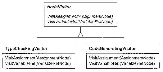
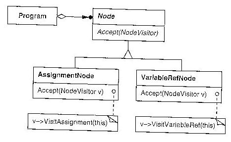
"Smoking Gun" Visitor Examples
-
At least one person
really hates the visitor pattern. Is it that bad?
lecture #24 started here
We only have time to mention the existence of these, but they are fun.
Some Final Thoughts on Patterns
These are from
Coplien's Paper.
- Emphasis on patterns is analogous to emphasis on associations instead of classes
- Patterns are about systems, not just individual components
- Patterns can form "microarchitectures"
- Patterns can be applied to other areas besides design (process patterns,
user interface patterns, teaching patterns, project organization
patterns...)
- Patterns can be "interdisciplinary" among different software areas.
- Patterns thrive on capturing and articulating points of complexity
(no complexity => no need for patterns). OOP needs patterns
worse than traditional structured programming because OOP tends
to be more complex than structured programming (e.g. dynamic
data-driven
relationships instead of static code-control-flow relationships).
- Patterns' immediate ancestor were "programming idioms"
- Idioms capture a solution to a problem in a context (= pattern)
- Idioms capture (language-specific) interactions between objects
- Design patterns capture language-independent interactions
- Patterns are about people, not houses, or software. The human
side is usually about either utility, or aesthetics. Software
designs tend to capture API's and data structures but miss nuances
of relationships; software process distances itself from unreliable
human beings.
- Human Software Pattern Example:
Simply Understood Code
Collaboration Diagrams
Collaboration Diagrams serve a similar role to sequence diagrams;
they and sequence diagrams are both in the category of
"interaction diagrams".
The following figure is from "Unified Modeling Language User Guide".
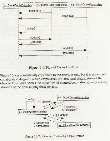
In addition to your text and whatever sources on the internet you may find,
take a look at the following sources:
Collaboration diagrams are semantically equivalent to sequence diagrams, but
are telling a sequential dynamic story atop (or "in the context of") a class
diagram, making it somewhat easier to relate them back to the class
diagrams. To create a collaboration diagram you start with a (subset of a)
class diagram and annotate it with specific sequences of method calls, which
are textually numbered to depict their ordering.
Why are collaboration diagrams useful?
These UML diagram types help connect the use cases and classes.
Each scenario (== sequence of steps for a use case description)
can lead to a collaboration diagram. The collaboration diagrams
in turn help identify missing classes, methods, and associations
for class diagrams.
Vertical and Horizonal Teams
Consider the major technical categories for your project (UI, database, etc.).
It is possible to organize teams around these categories, or around functional
tasks, each team being responsible for a set of related use cases. Which is
better, and why?
- Administration team
- account creation and management, user reporting
- Navigation team
- integration / user interface / map / activity selection
- Application Mechanics team
- develop content / activities / phases / gameplay
- Data team
- database, file and/or in-memory data structure representations
- Algorithms team
- problem solving from the internals point of view
- Help team
- develop automated and/or human-based help communications
- Network team
- develop inter-process communications as needed
Adjustments
- Individual Accountability
- This means WAR.
- Documentation vs. Demo vs. Delivered Functionality
-
- Documentation is empty without Implementation.
- Implementation is rhetorical without Delivered Functionality.
- Delivered Functionality is useless without Documentation.
- Are you a team?
- Did you meet with your team enough to sew your work together
into a coherent project? Division of labor is great, but integration
is harder and equally important. It will be part of your grade on
homeworks. It requires scheduling and not
everyone-goes-and-does-their-part-the-night-before-its-due.
- Produce readable design document(s)
- I have to be able to read and understand project documents! If you
can't format your diagrams to fit the page, or print a lot of text so
small I can't read it with my glasses on, or don't have enough toner
in your printer: fix it.
- The Master Design Document
- Although we want to emphasize agility :-) let's consider how
our agility might be compatible with a goal of having a design that
makes sense when viewed as a whole.
Consider the SSDD Template;
it has additional suggestions that may be useful, such as a
Requirements Traceability section that
maps from requirements elements to their corresponding design elements.
In fact, the main difference between doing it waterfall vs. doing it
agile is whether you do it all at once up front, or gradually. The
outcome should still be high quality software whose design is documented.
- Navigation Aids
- I won't even notice your project documents unless home pages, tables
of contents, or indices include pointers to the good stuff. For
example, how do I navigate and discover the many documents that
are accumulating in your SVN?
- File Formats
- Generally I might not bother to read/grade a document that I cannot
easily browse from my desktop linux machine. This affects .doc vs.
.docx, the use of Visio, etc.
- Produce an editable, electronic document
- Hand-drawn sketches are welcome. Whose job is it to scan them in
so that they are part of the project ? .jpg or .pdf files are
welcome. For us to be able to edit, we need the .dia or other
source files used to produce the .jpg or .pdf if there are any.
- Avoid "buzzword infection"
- Students learning software engineering or UML are exposed to many new
terms. When writing software engineering documentation, keep the
technical buzzwords out of your application domain descriptions unless
they really belong there. Example: in use cases you learn about actors,
so in your descriptions of the application domain, the word "actors"
starts being used to refer to many non-actor things.
Git Tip
If "git pull origin" is not working for you, you might try
"git fetch origin +master:master".
The Git tutorial says to use "git pull origin master".
The implication is that
the use of a default branch (master) might not work reliably,
or that there is no default branch.
Design Tools
Design Tools cover a wide range of functions ranging from UML drawing tools
to user interface builders. Anytime design tools come up, the phrase CASE
(computer-aided software engineering) is liable to get used. Ideally a CASE
tool would integrate and automate the many phases of software engineering,
including design. Since the waterfall is not realistic, ideally a CASE tool
would be able to show changes in UML diagrams that occur in the coding phase.
Earlier I was appalled to find that Eclipse didn't bundle a UML design
drawing tool. Now I am appalled to find the Eclipse doesn't really
bundle a Java GUI builder tool either! In both cases, we are supposed to
select, download, and install a plug-in. Eclipse.org apparently endorsed
and adopted a tool called Visual Edit, but the tool is not supported in
the current version of Eclipse, an indication that it (VE) is in trouble.
Dr. J's Reflection on UML Diagram Types
We need to spend some more time on getting the Details worked out for
our software design. UML is not going to magically solve that for us,
it is a set of diagramming notations, no more. Having said that, it
is the case that bad UML diagrams may make it more difficult for us to
accomplish our goal (of working out the details well enough to where we
will be able to implement them), and good ones may help.
Is an an activity diagram a special-case of a state chart?
In some student homeworks I have criticized a diagram for having states
that were not very well-defined, or too "verb"-oriented.
Activity diagrams are not statecharts. If you did an activity diagram,
don't call it a statechart, and I won't criticize it for sounding "verb"-ish.
A good class diagram...
- Conveys key relationships (associations) between classes
- not just inheritance and aggregation, but application domain
(and object communication) relationships
- Conveys enough detail to be useful in the implementation...
- not just class member variables and methods, but roles, multiplicity...
A good statechart...
- Has well-defined states, represented by a specific variable (or two)
in a (explicitly identified) class
- I should be able to see and understand what variable(s) in the class
diagram represent the states in the statechart.
- has states whose lifetime generally exceeds a single method.
- has states which affect the object's behavior
- Typical
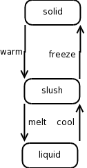
   class C(h2ostate, slushdegree)
      method precipitate(x,y)
          case foostate of {
          "solid": pileup(1.0)
          "liquid": drain(1.0)
          "slush": { pileup(slushdegree); drain(1.0 - slushdegree) }
          }
      end
A good activity diagram...
- conveys control flow details for a particular method...
- many of the states may be implemented as method calls in this or
another class... or they can be assignments, etc.
- would serve as pseudo-code allowing straightforward coding
- for every "fork", there had better be an identifiable "join", a.k.a.
"barrier". This is small-scale, or "fine-grained" concurrency.
If you really want to diagram true and persistent
concurrent threads or processes with synchronous or asynchronous
communication, look to other UML diagram types.
A good interaction (sequence or collaboration) diagram...
- shows "messages" (method invocations) which bounce control flow through
a number of objects in order to fulfill a given use case
- drills down to the specifics
- shows possibly many instances that
are involved
- can be tied back to the class diagram(s)
- it should be clear how each object knows the other object to whom the
sequence diagram shows it sending a message. Is it via an object
reference in class A (identified by an association line in the class
diagram)? If not, how does (the object from) class A know to send
(the object from) class B a message?
Dr. J's Musings on Design - from Past Homeworks
Please address these matters in your homeworks. Your grade will be
affected by how well you address them.
Should a class diagram be a connected graph? What does it mean if there
are several disconnected subgraphs, or classes with no associations at all?
Maybe/probably, it means there are relationships (associations) missing.
Just like use case diagrams need supporting use case descriptions which
are obviously more important than the diagram itself, class diagrams must
have a supporting text section which describes, in some detail in natural
lanuage, what each class and each association means. The admin team's
createAccount State Diagram has a pretty good example of this.
Can a statechart be an NFA, or does it have to be a DFA? Sorry, but you
have to either be a DFA, or you have to add mutually-exclusive
guards/conditions on your events, see Nav team's Activity State Diagram #1
for an example where the "Navigate Path" event needs guards/conditions.
A narrative story line? Maybe not, but understanding of the whole system
is affected by whether the connections between use cases, statecharts or
sequence or activity diagrams, and class diagrams are apparent. Ideally,
a use case would motivate the extra details included in the secondary UML
diagrams, which would motivate substantial content in the UML class diagram.
At least, when looking at diagrams I should know what use cases and class(es)
they belong to -- put in cross references, using an obvious naming or numbering
scheme. Include the whole thing, not just the recent work but the parts I need
from before in order to understand the new stuff.
Let me say it again: for each statechart, I want to know what class it
belongs to and what member variable(s) in the class diagram represent
the state information.
As details grow, don't be bashful about splitting your class diagram into
multiple views: one big-picture view and multiple close-ups-with-details
is the natural thing to expect.
What, no title? Yes, I actually expect you to label and identify your
work properly.
.docx? Please save as .doc, .docx is not multiplatform yet. Don't leave
Linux and Mac users in the lurch.
.png? Please include source files, I really mean it.
When do you split a state chart? When some states pertain to one object
and other states pertain to a different object, consider splitting the
statechart and do two statecharts that execute in parallel in the
respective objects. Example from the data types team: there was a tank
game, and it had a state chart for what we might call the "game control"
(i.e. what the player is seeing, the user interface) but some states seemed
to suggest (to me) that the objects in the game such as the tanks might
need to track their state (damaged, moving etc), but that needs to be done
in a separate statechart.
When do you know a design is not finished and you have more details to work
out? When you see a class with a name like "Hex Game", it not only needs
its own variables and methods, you also suspect that its a whole big
coarse-grained subsystem with other classes, associations, statecharts,
and so forth all missing and needed.
Remember how you are supposed to define major UML diagrammatic elements in
a supporting text description? This is not just for classes, it goes for
associations as well. And generally, associations often need more thought
in your class diagrams, teams often get associations wrong or they are just
missing.
The goal of things like activity diagrams or statecharts is NOT to restate
the same things listed in the usecase diagrams! It is to work out details
at a finer grain of detail, the "inside-the-objects" details, as opposed
to the use case descriptions' "user-eye-view" from outside the objects.
In addition to what I said last time about diagrams referencing related
items in other diagrams or text sections of the overall design document,
I would add that (duh) diagrams need enough clear title markings so that
they can be identified. Perhaps besides just a name, each diagram should
indicate its UML diagram type and have a brief explanation of what it
depicts.
A few thoughts on SWEBOK
- 12 chapters, free HTML
- requirements
- design
- construction
- testing
- maintenance
- sw configuration management
- sw engineering management
- sw engineering process
- sw engineering tools and methods
- sw quality
- related disciplines
Object / Component Design
Specifying the public interfaces (set of public methods) helps you:
- identify missing attributes and operations
- specify type signatures and visibility
- specify invariants
- specify preconditions and postconditions
The first two of these are absolutely necessary to get to the
implementation stage, while the latter two are vital in
debugging and/or proving a module's correctness.
Avoid These Design Problems
- Be sure I can tell who did what, especially for what you did.
- sequence trouble
- when it looks like an event triggers a prior event, the
diagram gets suspicious to me.
- block-copy-and-edit UML diagrams?
- bad idea; find a way to merge them
- new rhetorical and generic diagrams
- find a way to apply them to illustrate our situation concretely
- granularity issues
- many diagrams where the story does not yet tell enough details
for you to go and implement what you've designed
- supporting text
- teams that put in the supporting text to explain diagrams
generally get better grades than teams that don't.
- associations are still underrepresented minorities
- they need further elaboration, especially inter-team associations
such as DB and activity-related communications
Top Comments from the Past Semesters, by this point
- use case task granularity can be tricky
- software involves lot of tasks. You are probably be missing some use
cases. You need them to even get a handle on what classes you will need.
- class diagrams are really all about the associations
- you probably haven't worked out associations' details enough
- class diagrams are insufficient to express an OO class design
- you need detailed descriptions of the classes and associations
- classes are categorized as: entity, boundary, and control
- if you categorize yours, you may discover missing design elements
- states in statecharts are nouns
- a statechart depicts the different values of some member variables!
and under what circumstances those get assigned new values.
- when do you need a: collaboration or activity diagram?
- when your details for how to work out a step in a use case involve
several objects, or when their communication patterns are non-trivial
- when do you not need a sequence or similar diagram?
- when the logic described is trivial
LaTeX help?
Check out TeX Studio,
an "IDE" for TeX/LaTeX. Doesn't make it WYSIWIG, but provides various
forms of IDE help. You may want to experiment with LaTeX WYSIWYG tools
(there are some good ones)
but any tool must make changes that are minimal/human-readable or they
defeat the point of using LaTeX.
Project File Organization
Let's talk file organization.
Teams no doubt already have a top-level project directory.
They should contain src/ doc/ and web/ directories.
- src/ is for source code including
GUI builder generated files, project files etc.
- doc/ is for documentation.
- web/ is for html, php, etc.; it will
be the public face of your project.
- You can rename directories in SVN,
but its a pain and you should minimize it. Adding new
top-level directories or subdirectories is more OK.
- If src/, doc/ and/or web/ cannot
or should not be distinct or you think they will play
no meaningful role, we should discuss that now.
What's in Your Repository?
So some of these suggestions may not apply to your team,
but please consider whether any do.
- Should look like a software project repository, not a
homework assignment repository.
- Reorganize to address obvious missing holes, e.g. a requirements
document but no design document posted in the obvious place.
- Remove or rename homework-assignment directories.
- Remove old or obsolete files and directories.
- Files and directories should not have
spaces in their names -- makes it a pain to work with in shells, editors,
etc. Delete spaces or change them to underscore or hyphen.
example: "docs/Diagram Descriptions" should rename to
"doc/DiagramDescriptions" or similar/shorter.
- Files and directories should be case insensitive -
no makefile and Makefile in the same directory, etc.
- Review directory organization; simplify. Thank goodness if you are not
being forced to use idiotic directory structure by your language or IDE,
e.g. proj/src/projgui/src/, or proj/src/projgui/src/projgui
- Delete empty directories, or if they are sites for future planned expansion, put enough documentation (readme.txt, index.html or whatever) such that it is clear why they are there.
Mapping Models to Code
Each sprint you are allowed to do whatever requirements, design, coding,
or testing is highest priority for your team. When it comes to coding,
can you generate some, or most, of your code directly from your design?
The term transformation is used used sometimes for mapping
from model to code, or code to code. Compare with compilation.
How are the terms related?
Goals:
- implement all the use cases
- implement working subsystems based on the design
- refine, and flesh out aspects of requirements/design where necessary
- integrate subsystems to form a coherent whole
Working on an object design model, and turning one to code, involves many
transformations that are error prone.
Potential problems. You may need to...
- modify things to speed them up or make things more modular
- implement "associations" in varying ways, since languages do not
have associations, only models do
- who enforces required "contract" properties such as making sure
that parameter values are within valid range?
- new requirements show up during coding or later
- requirements not quite right, need to "adjust" on the fly
- design not quite right
- when we go to code, we discover some of these things
- add undocumented parameters that we need
- add extra class member variables
- pile up enough surprise changes...and the design doc gets worthless
Four Types of Transformations
- model transformations
- editing the class diagram.
Simplify or optimize a class diagram, correct it, or fill in missing parts.
The more code already written, the
more code may have to be changed or recoded to stay consistent.
- refactoring
- an improvement to the model, or more often to the code. Sometimes an
improvement to the code doesn't change the model, but usually it does.
If the model must be changed, sure, minimize such change. Updating code
and failing to update the model leaves other developers unaware.
Refactor in TINY incremental steps, and test each step, or risk
pandemonium.
- forward engineering
- generate the code from the model. often mechanical, or easy.
This is what we need to do right now. Review how to do this for
classes, inheritance, public vars (vs. private w/ getters and setters?),
aggregation, user defined associations...
- reverse engineering
- construct an object model from the code. This is often the first step in
a fix-the-legacy-program job. Note: some aspects of code are hard to
map back onto model!
Guidelines for successful transformations
- address a single criteria at a time.
- if you are improving speed, don't distract yourself by reorganizing
or refactoring your classes at the same time.
- keep your transformations local.
- change as few methods or as few classes as possible. If you change
the parameters of a function, keep both old and new around for testing
(at least for awhile). If you are changing lots of subsystems at once,
this is an architecture change, not a model transformation.
- validate each transformation
- maybe it looks easy and obvious, but maybe you missed something
Mapping associations to collections
Unidirectional one-to-one associations are the best special case,
you can implement them as a pointer.
Bidirectional one-to-one associations introduce a mutual dependency,
you can almost just use two pointers, but be careful of the methods
to establish and break such associations, to keep things consistent.
Things get interesting when multiplicity >1 is involved.
one-to-many
The many-folks may have a single reference back to the one,
but the one will need what--an array (often dynamically sized) of
references. For low multiplicities, this is almost what linked
lists were born for, but for higher multiplicities a linked list
is too slow. The example in Figure 10-10 in the text uses a Set
(really, a HashSet). Whatever language you are using, you will need
to study the container classes, and if you are using a strongly typed
language, understand how the container classes handle their generic,
polymorphic nature. For example, in C++ the way container classes
manage to work with any type is using templates. In C, one would
just break the type system and typecast pointers as needed.
How do Java's container classes (such as HashSet) handle this problem?
If we don't know, we better find out ASAP, and you-all should know it
well before the midterm!
A key point are the methods that establish (and break) the objects'
participation in a given association. In Figure 10-10 examine and
understand the dovetailing between the removeAccount in class
Advertiser and the setOwner in class Account.
many-to-many
Both sides have a collection, and sets of operations on both sides must
keep these collections consistent. See Figure 10-11. Many supreme
software engineering gurus
just throw up their hands and demand that a new class be introduced in order
to implement the association. Don't be surprised if a lot of things in
the UML model get turned into classes in the implementation, and don't
expect implementation classes to all have a mapping back to a model class.
Qualifiers
Earlier I have said "many" multiplicities can be reduced by using
qualifiers, which amount to introducing a hash table or similar
structure to look up references. The Java class for doing this might
well be called Map. Figure 10-12 is very interesting, but its UML
seems bogus.
Optimizing the Object Design Model
Direct translation of model to code is often inefficient. Inefficiency is
often due to redundant memory references. You may need to optimize access
paths between classes.
- repeated association traversal
- x.y.z.a, if it is done often enough, may warrant x having a direct
reference to z (or even, depending on its type, to a).
- replace "many" associations with qualified associations
- add hash tables or other means of quickly picking subjects from "many"
associations, if multiplicity is large enough, like >> 10
- misplaced attributes
- if a class has no interesting behavior, or is only referenced from
a single calling/owning class (for example some aggregations are like
this), it is a candidate for
absorption into the parent class. See the Person and SocialSecurity
example
- lazy construction
- if construction is slow and the object is not used in every single
execution, consider a proxy for it that constructs it only if it is
used.
- cache expensive computations
- for example, if method m() is called a lot and is slow, AND if m() is
a pure math function or you can otherwise prove it is safe to do so,
remember the results of previous calls to m() to reduce future calls.
(Dynamic programming).
A couple small Design-related Asides
Mapping Contracts to Exceptions?
A good object-oriented design may have "contracts" for method behavior,
most commonly a method may be said to require 0 or more preconditions,
and to guarantee 0 or more postconditions or invariants. In Java, you
may implement contracts by inserting runtime checks, which slow execution
down, and if the contract is violated a class can report it by generating
an exception. The better way to implement this is to allow such checks
to be easily turned on/off at compile time. And if you use exceptions,
be sure you handle them; one of the most irritating and common failures
in Java applications, which users really hate, are ExceptionNotHandled
errors. Aggressive use of throw/try/catch can increase your total code
size by 100%, but aggressive error handling is usually better than no
error handling, and you have the same problems in most languages.
Object Persistence
Basic idea: when objects (and UML relationships) have to survive across
runs, what do you do? Serialization is the act of taking some structure
and converting it to a string, from which the structure can be restored.
It works for both persistence and mobility of that structure across machines.
Java tends to support Serialization a lot.
- serialize whole universe
- simplest notion of persistence, used in early programming languages,
not very efficient/scalable
- serialize disjoint structures independently
- single database table might store mixed types of data.
Need a primary key to get the data back, still not super scalable.
- one table per class
- each table needs a primary key, may need lots of references across tables
(foreign keys). Keep it Simple, or go take the database course.
Pair Programming
- Are you supposed to actually do pair programming in CS 383?
Yes, at least once, for serious. More if it "works" for you.
- Before you judge it, learn how, and do it "right", as best you can.
Thoughts from Wray's
"How Pair Programming Really Works"
- driver-navigator metaphor - navigator is not just watching.
- "if you're doing it right, your screen should be greasy by end of the day"
- change drivers frequently
- rubber-plant effect ("self-explanation") supplanted by
"expert programmer theory" (prompting questions)
- Pair Programmers notice more details (change blindness)
- Fight poor practices (pair pressure vs. build-fix conditioning)
- Sharing and judging expertise (know your teammates' abilities)
Note also the ideas from
21 ways to hate pair programming.
Software Project Management
This discussion is intended to add depth to whatever we have said and done
about this topic so far. Managing a software project includes:
- Project planning
- requirements (which we did study), estimation and scheduling (which we
did not study much)
- Project monitoring and control
- how to keep the team and management up to date? how to stay on the
same page in the face of changes? Experience suggests that
management is often out of touch.
- Risk Management
- measuring or assessing risk; developing strategies deal with risk.
Strategies include: get someone else to take the risk, concluding
the project is not worth the risk, reducing the negative effect of
the risk, or being prepared to deal with what you see may come.
- Software Process
- We've under-discussed this aspect of SE. It is really all about
what procedures or structure are imposed on the humans doing the
software, in order for management to be able to have a chance of
tracking the project and knowing what's going on .
- Dealing with Problems
- Project managers, developers, and customers may introduce problems
which affect the whole project in different ways.
- If a project
manager doesn't know how to ... motivate their team members, or
- is so unrealistic in their estimation that the schedule is impossible,
or
- cannot deal with the conflict between schedule and quality concerns,
it can kill a project.
If developers
- don't know or don't bother to
learn the application domain they are asked to code for, or
- don't
bother to format or document their code or follow project standard
procedures for testing and check-in, or
- "panic/shutdown" under
deadline pressure
... that can kill a project. If customers
- keep
changing requirements, or
- don't have the funds to build what they need,
or
- don't have the time available that is necessary
the project can fail.
Experiences with Project Management
- My Ph.D. advisor ran a small team, about a half-dozen at its
largest. He was dictatorial and grumpy. He did not just lead by
giving orders or by verbal tirade though, he also led by doing many
menial tasks for the team that he was unwilling to ask a student
to do, because their time was too valuable. Respect your subordinates.
- My own (==grant/research) projects have ranged in size from 1-15.
As a manager I am constantly spread too thin. Some of my team members
get this, and some don't.
- Some team members are too independent, and some are too dependent.
Too independent means: I don't know what they are doing. Too dependent
means: they are basically trying to get me to do their job for them.
- I repeatedly encounter
a cycle that starts with quality concerns that need greater
review and intervention on my part, so I tell students I have to
look at, test and approve what they are doing, and then (ouch)
I become the bottleneck in the project (very, very bad). So then
I try to allow students enough autonomy to make forward progress,
and then bug reports from my customer raise quality concerns, and...
- Managing other programmers is like herding cats.
People-person skills are usually not taught in engineering colleges.
It is not enough to be "nice", but sometimes that helps. I struggle
with being too "nice". Some students or student employees will
exploit that. Then they
act surprised when they get fired from paid employment or get a
lower grade than others in a class.
- To inspire loyalty and hard work, you probably have to build a
relationship
with someone. It may not have to be a "we go to date movies" type
of relationship, but they have to feel you listen and care about
them. It is easier to do this with a paid employee than with a
student in a class. Many students do Not like to hang out w/ profs.
- Sometimes you have to "clear the air" with someone. There are some
conflict resolution techniques that work better than others. Not
threatening their reptile or mammalian brains, and making it clear
that you are dependably honest and not manipulative, seems to help.
- Some SE classes have been spectacularly more successful than
others, despite the instructor/manager not being smarter,
and not teaching that much differently from semester to semester.
Tools and processes may be the same, with way different outcomes.
No wonder
software project estimation and planning has such a poor track record!
- Having good (== smart) people helps in some ways, but I have seen
smart people who chose to be liabilities.
- Having teams where the folks really like each other helps a Lot.
Having teams where everyone is pulling their weight helps a Lot.
- I have seen teams with spectacular personality conflicts, sometimes
related to personal differences. There can be team members who are
much worse than merely "dead weight".
lecture #25 started here
Plans for Next Week
- Reminder: I will be at the ACM SAC conference next week and not in
class.
- You have coding and/or integrating to do, so I suggest that
you use your lecture-free time wisely.
- Despite no lecture, I expect you to meet and I expect scrum reports
MWF with attendance information, and WAR reports turned in this and next
weekend per usual.
- You can meet in class, or head to a more attractive
venue on campus as you please.
Project Scheduling
In addition to your textbook section on scheduling, check out
this
fine document which comes from the IT office of the
state of California. Among other things, it includes example
Gantt and
PERT charts.
You should read up on them.
A Gantt chart is a list of activities in mostly-chronological order,
side-by-side with an array of corresponding bar-graph timelines. It is good
for smaller projects. Compare with attaching a horizontal timeline to a
backlog task list, and graphing time estimates and dependencies.
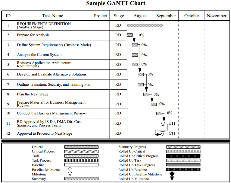
A PERT (Project Evaluation Review Technique) chart is believed to
scale better to larger projects; it gives up the linear list-of-activities
format in favor of an arbitrary task dependency graph. It is arguably
"better" than Gantt format in the same way that collaboration diagrams
might arguably claim to be better than sequence diagrams. In reality,
time information is pretty important so Gantt charts and sequence diagrams
both still have their place.

Each node in the
graph is annotated with schedule information. California's example uses
the format on the left; Visio provides the more detailed one on the right.
PERT charts can be processed computationally (like a spreadsheet), and
by applying the durations and dependencies to a particular calendar timeline,
the chart can be used to calculate the starts, ends, amount of slack, and
critical path through the chart.
| Task Name |
|---|
| task # | input
| | start date | end date
|
|
| versus
|
| early start | duration | early end
|
| | Task Name |
|---|
| late start
| slack | late end
|
|
|
Dr. J's take on the scheduling thing (have to try this some time):
- Make a task list, assign a time estimate to each task. For each task,
define the milestone/deliverable that shows the task is complete.
Rule of thumb:
don't try to break things down finer than 1 week's effort; smaller than
that and the planner/scheduler will spend the whole project just updating
the charts continuously.
- Identify the dependencies between task list items. Should end up
with a partial ordering (no cycles). The more dependencies, the less
parallelism and the harder it will be for more programmers to speed
things up.
- If you have a lone ranger, one-engineer project, the schedule
identifies the milestones at which pieces are delivered for
customer acceptance tests.
- On multi-programmer projects, a primary goal is to parallelize to
keep the whole engineering staff productive. Avoid keeping $100K/yr.
engineers waiting for others to finish their work.
- The larger the project, the more difficult it is to keep everyone
at work. Allow a lot of room actual times to differ from estimates,
and be prepared to put people to work on backup tasks when their
primary task is stalled waiting for another task to finish. In one's
schedule, one can attempt to identify "slack"
Introduction to Software Testing
Untested code is incorrect code.
All code is guilty until tested innocent.
- various internet pundits
Testing is the process of looking for errors (not the process of
demonstrating the program is correct). Bruegge gets more subtle,
calling testing a matter of looking for differences between the
design (expected behavior) and the implementation (observed behavior).
Passing a set of tests
does not guarantee the program is correct, but failing a set of
tests does guarantee the program has bugs.
Testing is best done by someone other than the person who wrote the code.
This is because the person who wrote the code would write tests that
reflect the assumptions and perspectives they have already made, and
cannot be objective.
Reading Assignment
Read or watch Guru99 links on
Kinds of errors include:
- Syntax & semantics errors
- typos, language misuse
- Logic errors
- I/O errors
- formatting & parsing failures, network handshake trouble, ...
- Design errors
- misinheritance
- Documentation errors
- program does one (reasonable) thing, document says another
lecture #26 started here
Software Testing Buzzwords
- software reliability
- probability P that a software system will not fail within time T
under specified conditions (hardware OK, power steady, etc.)
- failure
- any deviation from expected behavior;
when an erroneous state results in a discrepancy between the
specification and the actual behavior
- fault
- synonym for defect, or bug
- fault avoidance
- looking for bugs via static analysis, such as examining source code
or running a static bug checker (e.g. lint) or model checker
(e.g. ESC/Java)
- fault detection
- experiments during development to identify erroneous states and
their causes
- fault tolerance
- mechanisms for handling or recovering from faults at runtime.
- erroneous state
- manifestation of a fault at runtime
- test driver
- For component testing, a fake "main()" that simulates the
context in which a component will be run, and calls the test
component. The driver determines what gets tested in the component.
- test stub
- For component testing, a simulation of the child components
that are called by the component under test. Fake versions of
associated classes that this component interacts with. Fake
results of queries or computations (return values) that this
component can use for its test. All this fakeness means that
testing on "live" data after integration is often a whole new ballgame.
Testing Trumps Design
The big lesson [about testing]: every little bit helps. You don't have to be
perfect by any stretch, just stretch yourself more than where you are
currently, and then a bit more...
For some years, I've taught a software engineering course that used both XP
(eXtreme Programming) and RUP (Rational Unified Process; Rational is a
subsidiary of IBM specializing in computer aided software engineering tools).
Students had group projects, and half were XP and half were
RUP. The projects are not run in as controlled a fashion as those in the
paper, so perhaps I am missing something. However, in general I have not
seen a big difference in results between the two. The main indicator of
success is previous experience. Groups that have a couple of experienced
people do better than those without.
However, one group of people consistently did better with XP than with
RUP. This is a group with little programming experience. RUP did not work
for them because they had nobody who could act like an architect. They would
produce UML diagrams, but they were always wrong, so it was a waste of
time. However, when they followed XP, they produced (usually poor) working
code that had regression tests. Eventually they started to refactor
it. Because they always kept their tests working, they always made progress,
even if it was slow. XP worked much better for these groups than it did for
average groups.
I'd take a reasonable, automated test suite over a great design any day.
The one can lead to the other more easily. I'm not sure I'd recognize a
"perfect" test suite if it hit me in the face, but a team that tries to
improve it's testing has the best chance of success.
Source:
Patrick Logan; thanks to Bruce Bolden for the pointer
Different Kinds of Testing
Testing activities serve varying roles (for certain tests), not just for
the Developer, but also the Client Customer and the User.
Kinds of testing include:
- black box
- tests written from specifications, cast in terms of inputs
and their expected outputs
- white box
- tests written with the program source code in hand, for example, to
guarantee that every line of code has been executed in one or more tests.
- component inspection
- hey, reading the code looking for bugs is a form of testing, and it can
be very productive
- unit testing
- testing individual functions, classes, or modules
- integration testing
- testing how units interact; culminates in a structural test
- system testing
- functionality, performance, acceptance test, installation test
- regression testing
- re-testing, preferably automatically, all your past tests, because
fixing new bugs often reintroduces old ones.
Test Cases and Test Plans
Lecture notes material here is adapted from [Lethbridge and
Laganiere], and other sources.
Test Cases
A test case is a set of instructions for exercising a piece
of software in order to detect a particular class of defects, by causing
them to occur. It includes a set of input data and expected output.
A test case often involves running many tests aimed at that particular
defect to be detected.
A test case has five components, given below. The purpose for
this much detail is presumably to support reproducing and reviewing
the test results by a third party (for example, the boss, or more
likely the developer who must debug things) after the tester is finished.
- name
- location
- the full path name of the program
- input
- input data or commands. May be files, redirected keyboard input, or
a recorded session of GUI input, net traffic, database results, etc.
- oracle
- expected test results against which the execution may be compared.
If the expected output includes outgoing network traffic, graphical
display of certain pixel patterns, etc, it will be difficult to automate
the comparison, a comprehensive recording facility or a smart human
can do the job.
- log
- actual output from the test.
- restoration (optional)
- instructions on how to restore the system to its original state after test
(if needed)
- priority
- different tests have different priority which affects the order and
frequency with which they should be run.
This week's sprint explicitly requests that you develop a test plan.
Test Plans
A test plan is a bigger document than a test case that:
- describes how a system is to be tested,
- including the set of test cases that are used.
A test plan should be written before testing starts.
- It can be developed right after requirements are identified.
- The "extreme programming" community argues in favor of writing the
test cases first, before coding.
If you can't come up with satisfactory
test cases, you certainly don't know the problem yet well enough to code a
solution or know whether your program is in fact a solution.
Unit Testing
Motivation:
- reduce complexity of testing
- focus on smaller units
- divide and conquer
- easier to pinpoint/localize trouble
- potentially, allows things to be tested in parallel
Most important kinds of unit tests:
equivalence tests
boundary tests
- Focus on boundaries between equivalence classes.
- Reason: developers and routine tests often overlook boundaries
(0, null input, y2k, etc.).
- Note: Watch out for combinations of invalid input.
Two parameters
x and y might both have interesting values that separately would be
legal, but taken together denote an event that the code can't handle.
path tests
-
What is a flow graph? Can you draw one for a given piece of C++/Java code?
Is there a remarkable similarity between flow graph and "flow chart" or
"UML activity diagram"?
-
Path tests try to explore (many) different paths through the flow graph.
-
Trying to test
"all paths" leads to the topics of "coverage testing" and
"combinatorial intractability".
-
Path coverage may be tractable at the method level, even if it isn't
at the program level.
Unit Testing Frameworks: JUnit
For what its worth, JUnit looks different than it used to, and older
tutorials, or some of my old notes, might no longer be current. junit is now
written in terms of Java annotations.
Java Annotations in 30 Seconds
Syntax:
        @Name
        @Name(elem=value(,elem=value)*)
- More than just a comment, but may replace comments
- often a compiler directive
- Three built-in to java.lang (Deprecated, Override, SuppressWarnings)
- Can define your own
- Junit defines its own set (e.g. Test)
- May be attached to declarations and sometimes to (uses of) types.
- In our case, attached to special methods used for testing.
JUnit
- Lars Vogel's JUnit tutorial
-
- unit testing is the smallest and oftentimes first form of testing
- %code tested = test coverage, but 100% test coverage doesn't speak to
quality of testing nor imply that there are not bugs
- although unit tests imply testing only one function/class independently
of others, unit test suites are often used for various larger granularities
(integration testing, subsystem testing).
- Java unit tests are "typically" a separate project in a separate folder
from normal code
- simplest example:
// ...MyClassTest class ...
@Test
public void thisShouldDoExpected() {
   MyClass tester = new MyClass();
   assertEquals("test explanation", 0, tester.testedmethod(10, 0));
   ...test more stuff, perhaps focused on testedmethod()
}
- Instead of
@Test, you could say
@Test(timeout=1000) to fail after 1000ms
- how unit tests get invoked: by JUnitCore.runClasses()
package de.vogella.junit.first;

import org.junit.runner.JUnitCore;
import org.junit.runner.Result;
import org.junit.runner.notification.Failure;

public class MyTestRunner {
  public static void main(String[] args) {
    Result result = JUnitCore.runClasses(MyClassTest.class);
    for (Failure failure : result.getFailures()) {
      System.out.println(failure.toString());
    }
  }
}
- test suites: because there seldom can be only one
package com.vogella.junit.first;
import org.junit.runner.RunWith;
import org.junit.runners.Suite;
import org.junit.runners.Suite.SuiteClasses;

@RunWith(Suite.class)
@SuiteClasses({ MyClassTest.class, MySecondClassTest.class })
public class AllTests {

}
- See section 5 for a list of JUnit @Annotations and assertions
- Java Code Geeks' tutorial
- Mostly redundant, so you can skip this site with its irritating popups,
but I note that it illustrates the
@Ignore annotation as a way to skip test methods or test classes within a larger
suite.
- Java T point's
- Mostly redundant, so you can skip this site. It reminded me that you may have to
download a junit4.jar and add it to your CLASSPATH in order to run Junit.
In-class exercise: if we wanted test cases for our semester project, what
should be in them?
lecture #27 started here
Unit Test Examples
From stackoverflow.com:
public class PhoneValidator
{
    public bool IsValid(string phone)
    {
          return UseSomeRegExToTestPhone(phone);
    }
}
you might write
public void TestPhoneValidator()
{
     string goodPhone = "(123) 555-1212";
     string badPhone = "555 12"

     PhoneValidator validator = new PhoneValidator();

     Assert.IsTrue(validator.IsValid(goodPhone));
     Assert.IsFalse(validator.IsValid(badPhone));
}
- This is just a start.
- Two equivalence classes (true or false); no boundaries (almost-good,
just barely good, sort-of good, ambiguous whether good-or-not).
- How many phone number (patterns) would you need in order to
test a phone number validator "thoroughly"?
- The use of the Assert class is not a C-style assert(); it logs
results for summary reporting.
Here is a more complicated unit test (adapted from lostechies.com):
public class CalculatorTests
{
    public void TestPressEquals()
    {
        Calculator calculator = new Calculator();
        calculator.Enter(2.0);
        calculator.PressPlus();
        calculator.Enter(2.0);
        calculator.PressEquals();
        Assert.AreEqual(4.0, calculator.Display);
    }
}
- You can tell (enough) about class Calculator to see what is tested
- What is different about this unit test than the last one?
- What potential flaws might need improving?
Here is another example, from developerforce.com. It is testing a class
StringStack:
public class StringStack {
   public void push(String s){}
   public String pop() { return null; }
   public String peak() { return null; }
   public Boolean isEmpty() { return true; }
}
What is the point of these one-line method implementations?
/* Verifies that push(), pop() and peak() work correctly
 * when there is only 1 object on the Stack. */
static testMethod void basicTest() {
   // Instantiate a StringStack.
   StringStack stack = new StringStack();

   // Verify the initial state is as expected.
   System.assert(stack.isEmpty());

   // Set up some test data.
   String onlyString = 'Only String';

   // Call the push() method and verify the Stack is no longer empty
   stack.push(onlyString);
   System.assert(!stack.isEmpty());

   // Verify that the value we pushed on the Stack is the one we expected
   String peakValue = stack.peak();
   System.assertEquals(onlyString, peakValue);
   System.assert(!stack.isEmpty());

   // Verify the Stack state after pop() is called.
   String popValue = stack.pop();
   System.assertEquals(onlyString, popValue);
   System.assert(stack.isEmpty());
}
Test Plans a la Dr. J
The Test Documents
Test Plan
Scope, approach, resources, schedule. This is by definition given
in the ANSI/IEEE Standard for Software Test Documentation.
Is your test plan a product, or a tool? If you are using your test plan to
sell your software, e.g. to a company that will use it in-house, they may
want an impressive test plan to give them some confidence in your code. If
you are making a product that requires a government or
standards-organization approval, you may have to meet their standards.
Otherwise...
A test plan is a valuable tool to the extent that it helps you manage
your testing project and find bugs. Beyond that it is a diversion of resources.
- from [Kaner et al]
as a practical tool, instead of a product, your test documentation should:
- facilitate the technical tasks of testing. For example, the test plan
document might cover overall file organization and how to run the
full range of implemented tests. It may also help you to:
- improve coverage, don't forget items
- avoid unnecessary repetition
- improve communication about testing tasks and process
- provide structure for organizing, scheduling, and managing the testing
Test Case Specifications
These are documents, discussed in an earlier lecture, that list inputs,
drivers, stubs, expected outputs, etc.
Test Incident Reports
These reports give actual results from a test run; often they are given as
differences from expected output. These are similar to bug reports, and in
fact, bug reports can often be turned into test cases + test incident reports.
Test Report Summary
List the results of testing. Prioritize failures in order to marshall
developer attention and resources where they are most needed. Draw some
conclusions about the current state of the software.
Test Plan
The following outline is from:
TEST PLAN OUTLINE (IEEE 829 Format)
- Test Plan Identifier
- References
- Introduction
- Test Items
- Software Risk Issues
- Features to be Tested
- Features not to be Tested
- Approach
- Item Pass/Fail Criteria
- Suspension Criteria and Resumption Requirements
- Test Deliverables
- Remaining Test Tasks
- Environmental Needs
- Staffing and Training Needs
- Responsibilities
- Schedule
- Planning Risks and Contingencies
- Approvals
- Glossary
IEEE TEST PLAN TEMPLATE
TP.1.0 Test Plan Identifier
Some type of unique company generated number to identify this test plan, its
level and the level of software that it is related to. Preferably the test
plan level will be the same as the related software level. The number may
also identify whether the test plan is a Master plan, a Level plan, an
integration plan or whichever plan level it represents. This is to assist in
coordinating software and testware versions within configuration management.
Keep in mind that test plans are like other software documentation, they are
dynamic in nature and must be kept up to date. Therefore, they will have
revision numbers.
You may want to include author and contact information including the
revision history information as part of either the identifier section of as
part of the introduction.
TP.2.0 References
List all documents that support this test plan. Refer to the actual
version/release number of the document as stored in the configuration
management system. Do not duplicate the text from other documents as this
will reduce the viability of this document and increase the maintenance
effort. Documents that can be referenced include:
- Project Plan
- Requirements specifications
- High Level design document
- Detail design document
- Development and Test process standards
- Methodology guidelines and examples
- Corporate standards and guidelines
TP.3.0 Introduction
State the purpose of the Plan, possibly identifying the level of the plan (master etc.). This is essentially the executive summary part of the plan.
You may want to include any references to other plans, documents or items that contain information relevant to this project/process. If preferable, you can create a references section to contain all reference documents.
Identify the Scope of the plan in relation to the Software Project plan that it relates to. Other items may include, resource and budget constraints, scope of the testing effort, how testing relates to other evaluation activities (Analysis & Reviews), and possible the process to be used for change control and communication and coordination of key activities.
As this is the "Executive Summary" keep information brief and to the point.
TP.4.0 Test Items (Functions)
These are things you intend to test within the scope of this test
plan. Essentially, something you will test, a list of what is to be
tested. This can be developed from the software application inventories as
well as other sources of documentation and information.
This can be controlled and defined by your local Configuration Management
(CM) process if you have one. This information includes version numbers,
configuration requirements where needed, (especially if multiple versions of
the product are supported). It may also include key delivery schedule issues
for critical elements.
Remember, what you are testing is what you intend to deliver to the Client.
This section can be oriented to the level of the test plan. For higher
levels it may be by application or functional area, for lower levels it may
be by program, unit, module or build.
Software Risk Issues
Identify what software is to be tested and what the critical areas are,
such as:
- Delivery of a third party product.
- New version of interfacing software
- Ability to use and understand a new package/tool, etc.
- Extremely complex functions
- Modifications to components with a past history of failure
- Poorly documented modules or change requests
There are some inherent software risks such as complexity; these need to be
identified.
- Safety
- Multiple interfaces
- Impacts on Client
- Government regulations and rules
Another key area of risk is a misunderstanding of the original
requirements. This can occur at the management, user and developer
levels. Be aware of vague or unclear requirements and requirements that
cannot be tested.
The past history of defects (bugs) discovered during Unit testing will help
identify potential areas within the software that are risky. If the unit
testing discovered a large number of defects or a tendency towards defects
in a particular area of the software, this is an indication of potential
future problems. It is the nature of defects to cluster and clump
together. If it was defect ridden earlier, it will most likely continue to
be defect prone.
One good approach to define where the risks are is to have several
brainstorming sessions.
Start with ideas, such as, what worries me about this project/application.
Features to be Tested
This is a listing of what is to be tested from the USERS viewpoint of what
the system does. This is not a technical description of the software, but a
USERS view of the functions.
Set the level of risk for each feature. Use a simple rating scale such as
(H, M, L): High, Medium and Low. These types of levels are understandable to
a User. You should be prepared to discuss why a particular level was chosen.
It should be noted that Section 4 and Section 6 are very similar. The only
true difference is the point of view. Section 4 is a technical type
description including version numbers and other technical information and
Section 6 is from the User.s viewpoint. Users do not understand technical
software terminology; they understand functions and processes as they relate
to their jobs.
Features not to be Tested
This is a listing of what is NOT to be tested from both the Users viewpoint
of what the system does and a configuration management/version control
view. This is not a technical description of the software, but a USERS view
of the functions.
Identify WHY the feature is not to be tested, there can be any number of
reasons.
- Not to be included in this release of the Software.
- Low risk, has been used before and is considered stable.
- Will be released but not tested or documented as a functional part
of the release of this version of the software.
Sections 6 and 7 are directly related to Sections 5 and 17. What will and
will not be tested are directly affected by the levels of acceptable risk
within the project, and what does not get tested affects the level of risk
of the project.
Approach (Strategy)
This is your overall test strategy for this test plan; it should be
appropriate to the level of the plan (master, acceptance, etc.) and should
be in agreement with all higher and lower levels of plans. Overall rules and
processes should be identified.
- Are any special tools to be used and what are they?
- Will the tool require special training?
- What metrics will be collected?
- Which level is each metric to be collected at?
- How is Configuration Management to be handled?
- How many different configurations will be tested?
- Hardware
- Software
- Combinations of HW, SW and other vendor packages
- What levels of regression testing will be done and how much at each
test level?
- Will regression testing be based on severity of defects detected?
- How will elements in the requirements and design that do not make
sense or are untestable be processed?
If this is a master test plan the overall project testing approach and
coverage requirements must also be identified.
Specify if there are special requirements for the testing.
- Only the full component will be tested.
- A specified segment of grouping of features/components must be tested
together.
Other information that may be useful in setting the approach are:
- MTBF, Mean Time Between Failures - if this is a valid measurement for
the test involved and if the data is available.
- SRE, Software Reliability Engineering - if this methodology is in use
and if the information is available.
How will meetings and other organizational processes be handled?
Item Pass/Fail Criteria
What are the Completion criteria for this plan? This is a critical aspect of any test plan and should be appropriate to the level of the plan.
- At the Unit test level this could be items such as:
- All test cases completed.
- A specified percentage of cases completed with a percentage containing
some number of minor defects.
- Code coverage tool indicates all code covered.
- At the Master test plan level this could be items such as:
- All lower level plans completed.
- A specified number of plans completed without errors and a percentage
with minor defects.
This could be an individual test case level criterion or a unit level plan
or it can be general functional requirements for higher level plans.
What is the number and severity of defects located?
- Is it possible to compare this to the total number of defects?
This may be impossible, as some defects are never detected.
- A defect is something that may cause a failure, and may be acceptable
to leave in the application.
- A failure is the result of a defect as seen by the User, the system
crashes, etc.
Suspension Criteria and Resumption Requirements
Know when to pause in a series of tests.
If the number or type of defects reaches a point where the follow on testing
has no value, it makes no sense to continue the test; you are just wasting
resources.
Specify what constitutes stoppage for a test or series of tests and what is
the acceptable level of defects that will allow the testing to proceed past
the defects.
Testing after a truly fatal error will generate conditions that may be
identified as defects but are in fact ghost errors caused by the earlier
defects that were ignored.
Test Deliverables
Not all sections apply to all projects! Write only the ones that apply
to yours.
- Test plan document.
- Test cases.
- Test design specifications.
- Tools and their outputs.
- Simulators.
- Static and dynamic generators.
- Error logs and execution logs.
- Problem reports and corrective actions.
One thing that is not a test deliverable is the software itself that is
listed under test items and is delivered by development.
Remaining Test Tasks
If this is a multi-phase process or if the application is to be released in
increments there may be parts of the application that this plan does not
address. These areas need to be identified to avoid any confusion should
defects be reported back on those future functions. This will also allow the
users and testers to avoid incomplete functions and prevent waste of
resources chasing non-defects.
If the project is being developed as a multi-party process, this plan may
only cover a portion of the total functions/features. This status needs to
be identified so that those other areas have plans developed for them and to
avoid wasting resources tracking defects that do not relate to this plan.
When a third party is developing the software, this section may contain
descriptions of those test tasks belonging to both the internal groups and
the external groups.
Environmental Needs
Are there any special requirements for this test plan, such as:
- Special hardware such as simulators, static generators etc.
- How will test data be provided. Are there special collection
requirements or specific ranges of data that must be provided?
- How much testing will be done on each component of a multi-part feature?
- Special power requirements.
- Specific versions of other supporting software.
- Restricted use of the system during testing.
Staffing and Training needs
Training on the application/system.
Training for any test tools to be used.
Section 4 and Section 15 also affect this section. What is to be tested and
who is responsible for the testing and training.
Responsibilities
- Who is in charge (of each component of your test plan)?
- Divide the labor as appropriately as you can.
- Give everyone on your team something tangible they are responsible for
- If you have weaker links, assign them less critical components, or ones
that nothing else depends on.
This issue includes all areas of the plan. Who is doing each part?
Here are some examples:
- Setting risks.
- Selecting features to be tested and not tested.
- Setting overall strategy for this level of plan.
- Ensuring all required elements are in place for testing.
- Providing for resolution of scheduling conflicts, especially,
if testing is done on the production system.
- Who provides the required training?
- Who makes the critical go/no go decisions for items not covered
in the test plans?
Schedule
Should be based on realistic and validated estimates. If the estimates for
the development of the application are inaccurate, the entire project plan
will slip and the testing is part of the overall project plan.
-
As we all know, the first area of a project plan to get cut when it comes to
crunch time at the end of a project is the testing. It usually comes down to
the decision, "Let's put something out even if it does not really work all
that well."... And, as we all know, this is usually the worst possible
decision.
How slippage in the schedule will to be handled should also be addressed here.
-
If the users know in advance that a slippage in the development will cause a
slippage in the test and the overall delivery of the system, they just may
be a little more tolerant, if they know it.s in their interest to get a
better tested application.
-
By spelling out the effects here you have a chance to discuss them in
advance of their actual occurrence. You may even get the users to agree to a
few defects in advance, if the schedule slips.
At this point, all relevant milestones should be identified with their
relationship to the development process identified. This will also help in
identifying and tracking potential slippage in the schedule caused by the
test process.
It is always best to tie all test dates directly to their related
development activity dates. This prevents the test team from being perceived
as the cause of a delay. For example, if system testing is to begin after
delivery of the final build, then system testing begins the day after
delivery. If the delivery is late, system testing starts from the day of
delivery, not on a specific date. This is called dependent or relative
dating.
Planning Risks and Contingencies
What are the overall risks to the project with an emphasis on the testing
process?
- Lack of personnel resources when testing is to begin.
- Lack of availability of required hardware, software, data or tools.
- Late delivery of the software, hardware or tools.
- Delays in training on the application and/or tools.
- Changes to the original requirements or designs.
Specify what will be done for various events, for example:
Requirements definition will be complete by January 1, 19XX, and, if the
requirements change after that date, the following actions will be taken:
- The test schedule and development schedule will move out an appropriate number of days. This rarely occurs, as most projects tend to have fixed delivery dates.
- The number of test performed will be reduced.
- The number of acceptable defects will be increased.
- These two items could lower the overall quality of the delivered product.
- Resources will be added to the test team.
- The test team will work overtime (this could affect team morale).
- The scope of the plan may be changed.
- There may be some optimization of resources. This should be avoided, if possible, for obvious reasons.
- You could just QUIT. A rather extreme option to say the least.
Management is usually reluctant to accept scenarios such as the one above
even though they have seen it happen in the past.
The important thing to remember is that, if you do nothing at all, the usual
result is that testing is cut back or omitted completely, neither of which
should be an acceptable option.
Approvals
Who can approve the process as complete and allow the project to proceed to
the next level (depending on the level of the plan)?
At the master test plan level, this may be all involved parties.
When determining the approval process, keep in mind who the audience is:
- The audience for a unit test level plan is different than that
of an integration, system or master level plan.
- The levels and type of knowledge at the various levels will be
different as well.
- Programmers are very technical but may not have a clear understanding of the overall business process driving the project.
- Users may have varying levels of business acumen and very little technical skills.
- Always be wary of users who claim high levels of technical skills and programmers that claim to fully understand the business process. These types of individuals can cause more harm than good if they do not have the skills they believe they possess.
Glossary
Used to define terms and acronyms used in the document, and testing in
general, to eliminate confusion and promote consistent communications.
Test Case Examples
Many of the test case examples you will find on the web are provided by
vendors who want to sell their software test-related products. There are
whole (expensive) products specifically for Test Case Management out there.
Such commercially-motivated examples might or might not be exemplary of
best practices. You can evaluate them to some extent by asking: How well
does this example fulfill the criterion given by Dr. J above?
Examples
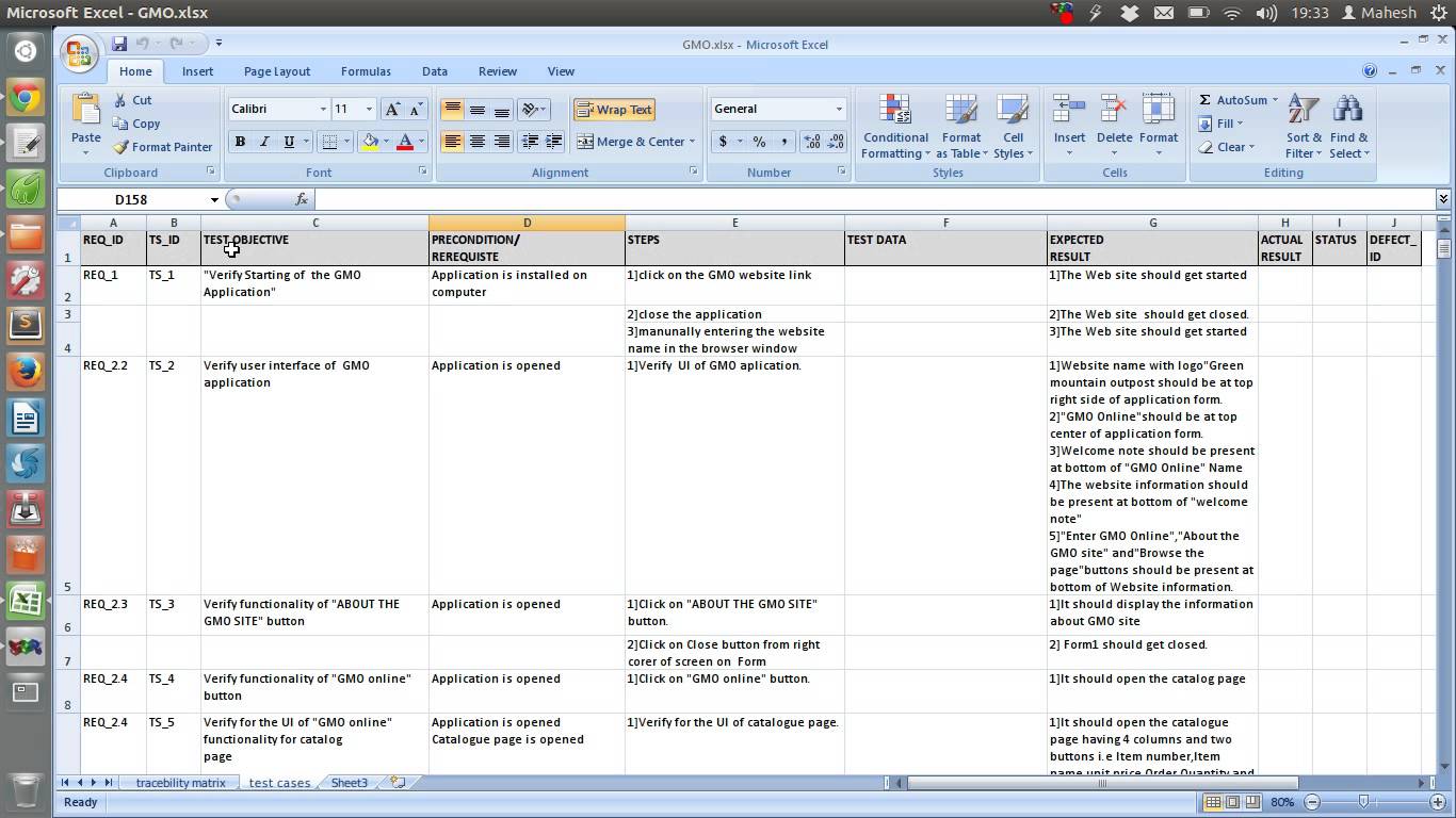 | manual test case instructions
|
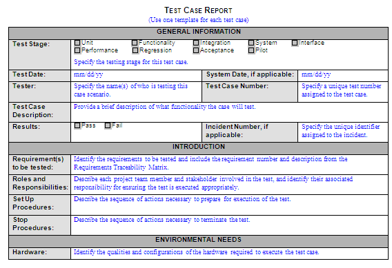
| test case report from Vietnam Testing Board
|
 | manual test case
|

| alleged Microsoft-derived test case format
|
|
foo
| OpenOffice Test Case Template Example (thanks Cindy and Leah)
|
What To Do?
What do we want to do for our class? We want test
cases that are readable, repeatable, and relevant. These criterion
include printable in report form,
traceable back to specific requirements, and readily
evaluable as to whether they turned up a problem or sadly, failed to do so.
Are there any obvious tools we should be using? If you have a choice between
manually documenting your test cases and adopting a tool for it, what are
your tool options and which would you prefer?
Among the most interesting open source candidates there are
- Unit test tools?
- Do our Unit test tools include test case management? Are they
generalizable to all types of tests, not just unit tests?
- STAF
- Software Test Automation Framework
- TestLink
-
- Test Manager plugin for Trac
- If you use Trac, this might be good
- What other tools do you know, or can you find?
Example of (white box) testing: Testing Loops
If your job is to write tests for some procedure that has a loop in it,
you can write tests that:
- skip the loop entirely
- execute only one iteration of the loop
- execute two iterations
- execute M iterations, for some random 2 < M < N-1
- execute (N-1), N, and (N+1) iterations
where N is the maximum number of allowable passes.
Reading Assignment
- Read Steven Anderson's Best and Worst Practices
- This is a short article based on the premise that unit tests are
specifically for the purpose of test-driven development.
Jot down a short list of things you agree with, things you disagree with,
or questions based on this article.
Catching Serial Bug Artists
- A SE author named Lethbridge makes an unfortunate analogy between
programmers and criminals; they have a modus operandi
- once you
find what type of bugs a programmer is writing in one place, the programmer
may well repeat similar bugs elsewhere in the code.
- Arguably true in some cases, not so in others
- Viewing a bug report as a crime scene has its metaphorical value
- worth reviewing all the code that was written/committed with (i.e. same
author, committed <= Ε time of)
a given bug once it is identified.
In selecting test cases, look for equivalence classes
You usually cannot test all the possible inputs to a program or parameters
to a procedure that you wish to test. If you can identify what
ranges of values ought to evoke different kinds of responses,
it will help you minimize test cases to: one representative from each
class of expected answer, plus extra tests at the boundaries of the
equivalence classes to make sure the ranges are nonoverlapping.
Wikipedia says we have a lot of Unit Test tools to choose from, which
do we use? Teams should
evaluate and select the tool that will work best for you.
lecture #28 started here
WAR Issues
- Git/github/rogue developer troubles
-
- How many folks are comfortable committing changes
- How many folks are working successfully in their own private branch?
- How many folks are breaking the build for others?
- Team attendance/participation troubles
- What I can expect, what you can expect, how to improve the situation?
- Docs vs. Code
- Agile emphasizes working code over docs. Does that mean you don't
have to document or update documents? Your time budget should spend
more time on code than docs, but it is not 100% vs. 0%.
- How to Document Work Accomplished/Delivered for a Sprint Report?
- Sprint report should be organized in terms of backlog items assigned
and completed. Pointers to delivered/committed code. How the code
was determined to be "done" (testing, metrics, review, demo)
Some (Lethbridge) Bug Categories
Purpose of this list: construction of (mostly white box, mostly unit-)
test cases. A thorough white box tester might perform and document
having performed the following examination of the code to be tested.
For each unit to be tested
For each category given below
Can this kind of bug occur in your unit?
For each place where it can, write one or more test cases that looks for it.
- Incorrect logic
- < instead of >; missing an = somewhere, etc.
- Performing a calculation in the wrong place
- such as: work done before or after a loop that needed to be in a loop
in order for it to be correct.
- Not terminating a loop or a recursion
- except in special circumstances, every loop can be checked to make sure
it makes forward progress towards a termination condition
- Not establishing preconditions; not checking your inputs
- examples: an integer is passed that is out of range; a string is passed
that is too long or not well-formed.
- Not handling null conditions
- often a by-product of a failure of an earlier routine
- Not handling singleton/nonsingleton conditions
- if "there can be only one", how do you ensure it?
- Off by one errors
- common in array indexing, novice code, translated code
- Precedence errors
- beyond "times is higher than plus", it is unwise to leave off parentheses
- Use of bad algorithms
- how do you test for badness? There is bad="too slow". There is
bad="doesn't always succeed", "bad=answer sometimes wrong", and variants.
- Not using enough bits/not enough precision
- when, for example, are 32-bit integers not enough?
this would seem to be statically checkable.
- Accumulating a large numerical error
- a specialty province, for some codes it is an urgent topic and the subject
of extensive testing
- Testing for floating point equality
- Duh. If they are calculated, float f1 is almost never == float f2.
Don't check if x == 0.0, check if abs(x) < 0.000001 or whatever.
- Deadlock/livelock
- Classic bugs for threaded programs. Special case of "incorrect logic".
- Insufficient response time (on minimal configurations)
- Do you test on the slowest machine that you must run on? If not, can
you write artificial tests to simulate that level of performance?
- Incompatibilities with specific hardware/software configurations
- Do you test on every HW/SW configuration you must run on? To what
extent can you automate this?
- Resource leaks
- Do you close and free every OS or window system resource you use?
- Failure to recover from crashes
- Do you test the whole "crash" experience and ensure that things come
back up gracefully?
Coverage Testing
Coverage means: writing tests that execute all the code. Since a significant
portion of errors are due to simple typos and logic mistakes, if we execute
every line of code we are likely to catch all such "easy" errors.
There are at least two useful kinds of coverage: statement coverage
(executing every statement), and path coverage (executing every path
through the code). Statement coverage is not sufficient to catch
all bugs, but path coverage tends to suffer from a combinatorial
explosion of possibilities. Exhaustive path coverage may not be
an option, but some weaker forms of path coverage are useful.
Coverage testing clarification: "all possible paths" is impractical
due to combinatorial explosion. "all nodes" is inadequate because it
misses too much. The right compromise is "cover all edges".
Example coverage tools:
- JaCoCo
- JaCoCo is one of the
newer tools that is more likely to actually run against recent/current Java.
- Clover
- This tool has been bought out and moved around, check out its video though.
Clover is a commercial product which works by instrumenting the source
code. It does statement and branch coverage, but not most of the
other forms of coverage. It might actually be cool.
- Hansel
- Hansel is an open source extension to JUnit, based on code developed at
the University of Oregon. It works with bytecode not source code.
It appears to just do statement coverage. Its not much, but its free
and its better than nothing.
- Cobertura, Quilt, NoUnit, Jester, jcoverage, etc.
- Emma, from the
ever-popular Source Forge.
- JaCoCo (above) may be related to or derived from Emma?
- Another commercial coverage tool is
JCover, which does
more types of coverage tests.
- There are no doubt dozens of others.
- Where are (free) C++/Python/etc. Coverage Tests?
- Additions/updates to this list are welcome.
More on Coverage Testing
Steve Cornett
gives a nice summary of several kinds of coverage testing, including
some reference to the different subsets of path coverage that have
been proposed to make it practical.
Note that although these are phrased as
yes/no questions, a coverage tool doesn't just answer yes/no or even
give you a percentage: it gives you a percentage and shows in detail
each location or case in which the coverage property did not hold.
- statement coverage
- measure % of executable lines that were executed by the tests.
A good starting point with many weaknesses. Examples:
- not all of a short-circuit boolean expression may have been tested
in 100% statement-coverage.
- If an if statement has no else clause,
100% coverage does not include: is the "then" ever not taken?
It is a challenge to even get this much coverage.
- function coverage
- did you execute every function? Weaker than statement coverage, but
maybe easier.
Function coverage would reveal if a function / interface was totally
broken. Examples:
- test that shared library entities are callable.
- catch method body stubs designed to blow up, and spectacular errors
- call coverage
- did you execute every (expression where there is a) call to every
function? Seemingly weaker than statement coverage,
except that there can be calls that are skipped by short-circuits.
- loop coverage
- did you execute every loop 0, 1, and >1 times? Complementary
to and non-identical to statement coverage. What other coverages
might you invent that are similar to loop coverage?
- relational coverage
- did you test every relational operator with equal, lesser-, and
greater-than values, in order to avoid off-by-one errors and
logic inversions? Expression-level coverage would be finer than
statement level coverage. Certain aerospace and military standards
would require this level.
- data coverage
- did every variable actually get referenced? every array element?
was every pointer followed? (Thought question: what kinds of bugs
might this coverage help find?)
- decision coverage
- evaluate every (outermost level) boolean expression to both
true and false. a.k.a. branch coverage. May find things missed
in statement coverage (for example, the proverbial
check-if-then-part-is-skipped), but still doesn't cover short circuit code
- condition coverage
- check whether individual boolean subexpressions were evaluated to both
true and false. This is "micro" or "atomic" scale coverage.
Will detect if short circuits are being skipped. Does not
guarantee decision coverage!?
- multiple condition coverage
- check whether all possible combinations of boolean subexpressions were
executed. Effectively, it is small-scale (statement- or expression-level)
path coverage. Scoring well requires a lot of test cases.
- condition/decision coverage
- union of condition coverage and decision coverage
- modified condition/decision coverage
- verify every condition can affect the result of its encompassing
decision. If it can't, why is it in the code? Likely a logic bug.
By definition, short-circuit conditions fail this test.
Invented at Boeing; required for certain aviation softwares.
- path coverage
- check if each possible paths in each function have been followed.
A path is a unique sequence of branches from function entry to exit.
Loops introduce an unbounded number of paths. # of paths is
exponential in the number of branches. Some paths may be impossible.
Many many variations introduced to try and develop "practical" path
coverage methods.
A couple other useful resources are Marick's
a Buyer's Guide to Code Coverage Terminology, and the related
How to Misuse
Code Coverage.
A Note on the Java "extends" keyword
One night long ago when I tried to make the students' software engineering
project, I came across a baffling error that looked like:
StarSystemGame.java:4: cannot resolve symbol
symbol  : constructor Game ()
location: class Game
  {
  ^
1 error
It seemed to be complaining that Game() must provide a default constructor
in order for any subclass to be allowed. But Game() should not have a
default constructor, so I tried hard to understand why Java complains.
In looking for an answer, I first looked at other code in our project
that was doing "extends" to see if it would show how to "do things right"
so it would compile. I game across the following bogosity:
   // Constructor methods
   /**
    * This empty constructor method was added by the Galactic and Province
    * Team to allow Sovereign to extend Charactr.
    */
   public Charactr()
   {

   }
This pretty much proves that the error is common, and that one "solution" is
to add a default constructor that makes no sense. But, wanting a better fix
and some understanding, I went to google, and after some searching, came
across some notes from
Stanford which pretty much explain the situation.
In brief: the compiler error message seems to blame the parent for the
child's mistakes (a common pattern in the real world). The correct
solution is
- ALWAYS DEFINE A CONSTRUCTOR FOR THE SUBCLASS.
Without it,
Java supplies a default constructor which calls the superclass default
constructor (which doesn't exist and generates an error message). This
issue is compounded by the fact that
- JAVA DOES NOT INHERIT CONSTRUCTORS.
The reason the child got a default constructor added was because it did not
inherit the parent's constructor.
This analysis got StarSystemGame compiling OK by adding the constructor:
  public StarSystemGame(String sourceFile) {
     super(sourceFile);
     }
I thought I was done, and feeling pretty clever, but there was one problem:
subclass Sovereign DOES define its constructor. And taking out the
dummy constructor from Charactr.java still causes Sovereign.java to fail.
Darn!
I thought: maybe since Java doesn't inherit constructors, the subtype must
define all the same constructors its supertype does, but that didn't work.
Then I thought: maybe the subclass constructor always calls a superclass
constructor, and if you don't do it yourself, it gets done unto you. This
seems to be the case. So for class Sovereign to compile OK without the
bogus superclass Charactr default constructor, subclass Sovereign's
constructor has to call a superclass constructor. The following works,
although I was just guessing at the parameter names due to TERRIBLE
PARAMETER NAMES IN THE Charactr CONSTRUCTOR!
   super('?', name, combatRating, 0, (Environ)null, "", "", "", "", "",
         enduranceRating, 0, leadershipRating, 0, 0, 0, false);
Questions: what is the "scom" parameter? Characters do not have a
space combat value (they do have a space leadership value). The
constructor is confused about this because class Unit requires all
units to have a space combat value. The spacecombat attribute should
be moved down into class MilitaryUnit where it belongs. This got me
wondering whether that first Charactr constructor was being used at all.
Apparently not. Sovereign constructors were being passed a space leadership
rating, but the superclass didn't seem to have a field to store it in.
I added spaceLeadership to class Charactr. Code for parsing characters
from .dat files probably needs to know about space leadership and do the
right thing with it.
Public versus Accessors
In reading past students' homeworks, I noticed there is a temptation for
teams to declaring "everything is
public". While public methods are normal, public fields are only normal
in a rapid prototyping context. For this reason, I am not surprised to see
the actual Java code using lots of privates where the design claimed
fields were public. One point I would like to reiterate is: if a
field is public there is no reason to write accessor get/set methods.
In fact, a big advantage of declaring a field public for rapid prototyping
purposes is that you get to defer writing these methods.
How Test Plans Fit Into the Big Picture
- This sprint "must include a test plan effort"
- But that's not all you are doing...
- Next Tuesdays sprint report will include longer time allotment because...
- Next sprint report had "darn well better" include a demonstration
of: a movement, a combat, and a mission. Textual prototype if necessary,
graphical prototype or close-to-real if possible.
- ask questions, read lecture notes
- take a first stab at a "test plan", and refine from there, with feedback.
- iteratively create and refine project documents just like we
do code
- each sprint may include coding goals, testing goals, and
documentation goals.
- At the end of the semester, or preferably sooner,
we should have accomplished the full set of documents and code for the
whole project.
Jeffery's conjecture:
Customers will only buy-in to a newfangled development process when they
see it gives them some convincing combination of more control, better quality,
and/or less cost. Agile methods may focus more on customer and product than
on documentation, but documentation remains a key element in
communicating with the customer.
Usability Testing (Bruegge 11.4.2)
- Tests the user's understanding of the system
- Find differences between system and user's expectations of what it should do (principle of least surprise)
- empirical: sit "typical" users down in front of the system or a
simulation of the system user interface
- observe or record users' interactions
- time how long they take, observe errors or difficulty performing a task
- solicit user's feedback afterwards
- process: develop test objectives, train users, conduct experiments, collect data
- even a few "discount usability tests" are better than none at all...
Three types of usability tests:
- scenario test
- give users the vision, see how difficult it is for users to understand
the scenario.
- prototype test
- vertical prototype would do one whole use case in detail.
horizontal prototype would do one layer (say, UI, without
underlying functionality)
- product test
- use a functional version of the system. only available after it is
implemented, but oh by the way, output of usability test will tell
you possibly many or major things to revise in your user interface.
(CS majors are not always good at usability!)
state-based tests
Developed for OO systems. Compares end-states of the system after a set of
code is executed, instead of comparing outputs. Derive test cases from a
UML statechart. Test every transition in the statechart. See Figure 11-14.
State-based testing is harder than it would seem; it is hard to automatically
generate the inputs needed before the test that are to put the system in the
state needed in order to test a given transition.
polymorphism and testing
If you use "virtual" methods and/or polymorphism, how does it affect your
testing strategy? Need to execute a given polymorphic code with all of its
possible runtime types. Example (Fig 11-15): your network interface has
open/close/send/receive methods, it is an abstract class with several
concrete implementations. Test the clients that use the network interface
against each of the concrete implementations.
From Use Cases to Markov Chains to Software Testing
This section is inspired by Axel Krings, who referred me to a paper
by James Whittacre and Jesse Poore.
Suppose you layout a finite state machine of all user activity, based
on your use cases. You can
estimate (or perhaps empirically observe) the probabilities of each
user action at each state. If you pretend for a moment that the actions
taken at each state depend only on being in that state, and not how you
got there, the finite state machine is a Markov chain. While
user actions might not really follow true Markov randomness properties,
the Markov chain can certainly be used to generate a lot of test cases
automatically!
lecture #29
Integration Testing
There are several ways to test combinations of units.
Big Bang
The "big bang": what happens when you link it all together? This has
the advantage of not requiring any additional test stubs that would be
needed to test partially integrated subsystems. But when things go wrong,
you have a needle in a haystack problem of finding the bugs.
Top Down
Top down = work from the user interface gradually deeper into the system.
This is a layered, breadthfirst approach. Advantage: it is more "demo-able"
for customers. Subsets of functionality may become usable before the whole
system integration is completed.
Bottom Up Testing
Bottom up = test individual units first
Focus on small groups (2+) of components. Add components gradually.
Advantage: it is more debuggable and emphasizes meat-and-potatoes
over shallow surface behavior.
Sandwich Testing
Sandwich testing selects a "target layer" and tests it against the layers
above and below it. New target layers are selected to generate additional
tests until the whole system has been tested. If the target layers are
selected to gradually work from top and bottom into the middle, then
sandwich testing is a combination of top-down and bottom-up testing.
Questions:
- If your method computes a return value, how do you check it?
- If your method modifies a class variable, how do you check it?
- If your method writes to a file, or a network, or a window,
how do you check it?
- If your method is in the middle of a multi-stage operation,
how do you check it?
- If your method is in the middle of a time-sensitive operation,
how do you check it?
More on Integration Testing
Generally, integration is when two or more developers (or teams) are
combining their work. This is typically also the phase at which GUI events
can be meaningfully tested.
During the latter part of integration testing, use cases may be walked
through manually, confirming the correct events are invoked based on
input. Use case tests at this point are run as
independently as possible with minimal setup, to observe the
behavior of each use case independently of the others.
What Do Integration Tests Looks Like?
A set of integration tests would:
- consist probably of a directory, possibly with subdirectories
- include a short rationale explanation of how they are organized
- test pairwise combinations of units or subsystems, with test
harnesses that resemble unit tests
- may emphasize more heavily those integrations that are most likely
to be error-prone, such as where subteams' work must call other subteams
Note that from
http://hissa.nist.gov/HHRFdata/Artifacts/ITLdoc/235/chapter7.htm
there is a good observation, relevant to integration testing:
as component/subsystem size increases, coupling among sibling
components should decrease. If a system design follows this principle,
most integration tests will be near the leaf units.
Functional Testing
Not as in "functional programming", rather as in "testing functionality".
The functional testing phase is where usage of the software system is tested
to a much higher degree. Rather than testing each use case individually,
there will be a variety of users selected to attempt to use the software for
its original intended purpose with various supported situations and goals.
This will produce a very large variety of permutations of use cases, and
allow us to observe how the use cases behave when used together.
What does an end-user system test look like?
Consider this
fragment from the Unicon checklist.
System Testing
Tests the whole system. There are many kinds of system tests.
Functional (requirements) testing
Looks for differences between the requirements and the system.
This is traditional blackbox testing. Test cases are derived from
the use cases. Try to create test cases with the highest probability
of finding the bugs the customer will care about the most.
Performance testing
This tests one of the non-functional requirements. Typically, a system
will be tested to see if it can handle the required userload (stress test)
with acceptable performance...which may require a fairly elaborate fake
user environment; consider what it would take to test how a web server
handles lots of hits.
Other forms of performance testing include volume testing (how does the
system handle big input datasets), security testing (by "tiger teams" ?),
timing tests, recovery tests (e.g. artificially crash the network or
other external resource).
Pilot test
Also called "field test", these tests may go out to a progressively larger
number of real customers.
- alpha test
- Features are frozen for a pending delivery. Extensive in-house
testing that tries to simulate an end-user experience. Bug reports
come in and are fixed furiously. Often a crunch time-causer.
- beta test
- Features remain frozen. Software is delivered/installed/operated
on end-user hardware, with "friendly" customers who agree to provide
detailed bug reports.
- closed beta - beta customers are hand-selected ("by invitation")
- open beta - beta customers are self-selecting ("masochists")
Testing Odds and Ends
We will probably scratch our way through a few more testing topics
as needed in future lectures.
Acceptance test
Benchmark tests, possibly against competitors or against the system
being replaced (shadow testing). A specialized team from the customer
may be involved in the evaluation of the system.
Installation test
Anytime you install a program on a new computer, you may need to
verify that the program is running in the new environment. Software
is often shipped with a self-check capability, which might run when
first installed and then disable itself. More paranoid software
self-checks every time it is executed, or even periodically during
execution.
Managing test activities
Planning the testing process
Start the selection of test cases early; parallelize tests.
Develop a functional test for each use case. Develop test
drivers and stubs needed for unit tests. Some expert (Bruegge?)
says to allocate 25% of project resources for testing -- do you agree?
Where we are At, Where we are Headed
At Microsoft there used to be the mantra:
Windows isn't done until Lotus won't run.
In software engineering class, we could have a highly unrelated and less
catchy saying
your 383 work is not done until it is documented, findable (i.e. by Dr. J
navigating in the repository) and reproducible (i.e. others can build/run/test
successfully, not just the author).
- There are 2.5 weeks of class left.
- 2 Goals: demo finished product, document what has been done.
- If your work is not shown in your team's demo, you are encouraged
to make an appointment with me and discuss your contribution to the
project during finals week.
- Final Review Friday May 6.
- Demo Day: Wednesday May 4. 12 minutes per team to show me your best work
- Final Exam Tuesday May 10 from 10-12
- Final Project Documentation due Friday May 13, 5pm.
Final Project Document
This is a team document with chapters on requirements, design,
implementation, testing, and metrics.
Teams are encouraged to provide a pre-final draft early enough to
incorporate feedback into your final result.
Example
Your team knows it has to do unit tests, so you do them. Now, how does Dr. J
grade you on that part?
A: your end of semester project document includes a "chapter" describing
your testing. It has a section on unit tests. The section gives the number,
(file)name(s), and location(s) of the unit tests within the repository,
along with instructions for rerunning them and a sample screenshot showing
a junit output summary.
Inspections
Idea: examine source code looking for defects.
Roles:
- author
- moderator
- runs the meeting. establishes and enforces the "rules"
- secretary
- recording defects when they are found
- paraphrasers
- step through the document, explaining it in their own words
Myers' Checklist for Code Inspections
Figures 3.1 and 3.2 of [Myers] give a list of low-level things
to look for.
| Data Reference | Computation
|
- Unset variables used?
- Subscripts within bounds?
- Noninteger subscripts?
- Dangling references?
- Correct attributes when aliasing?
- Record and structure attributes match?
- Computing addresses of bit strings?
Passing bit-string arguments?
- Based storage attributes correct?
- Structure definitions match across procedures?
- String limits exceeded?
- Off-by-one errors in indexing or subscripting operations?
- Computations on nonarithmetic variables?
- Mixed-mode computations?
- Computations on variables of different lengths?
- Target size less than size of assigned values?
- Intermediate result overflow or underflow?
- Division by zero?
- Base-2 inaccuracies?
- Variable's value outside of meaningful range?
- Operator precedence understood?
- Integer divisions correct?
|
| Data Declaration
| Comparison
|
- All variables declared?
- Default attributes understood?
- Arrays and strings initialized properly?
- Correct lengths, types, and storage classes assigned?
- Initialization consistent with storage class?
- Any variables with similar names?
|
- Comparisons between inconsistent variables?
- Mixed-mode comparisons?
- Comparison relationships correct?
- Boolean expressions correct?
- Comparison and Boolean expressions mixed?
- Comparisons of base-2 fractional values?
- Operator precedence understood?
- Compiler evaluation of Boolean expressions understood?
|
| Control Flow
| Input/Output
|
- Multiway branches exceeded?
- Will each loop terminate?
- Will program terminate?
- Any loop bypasses because of entry conditions?
- Are possible loop fallthroughs correc?
- Off-by-one iteration errors?
- DO/END statements match?
- Any nonexhaustive decisions?
|
- File attributes correct?
- OPEN statements correct?
- Format specification matches I/O statement?
- Buffer size matches record size?
- Files opened before use?
- End-of-file conditions handled?
- I/O errors handled?
- Any textual errors in output information?
|
| Interfaces
| Other Checks
|
- Number of input parameters equal to number of arguments?
- Parameter and argument attributes match?
- Parameter and arguments UNIT SYSTEMS match?
- Number of arguments transmitted to alled modules equal to number
of parameters?
- Attributes of arguments transmitted to called modules equal to
attributes of parameters?
- Units system of arguments transmitted to called modules eual to
units system of parameters?
- Number, attributes, and order of arguments to built-in functions correct?
- Any references to parameters not associated with current point of entry?
- Input-only arguments altered?
- Global variable definitions consistent across modules?
- Constants passed as arguments?
|
- Any unreferenced variables in cross-reference listing?
- Attribute list what was expected?
- Any warning or informational messages?
- Input checked for validity?
- Missing function?
|
Source: Glenford [Myers], "The Art of Software Testing".
How do we normalize class participation?
It is typical in 383 that some folks are doing far more of
the work than others. This can be for any number of reasons, some more
sympathetic than others. Basic goals:
- every team member has a voice
- every team member should contribute something real, that reflects
their best effort and their abilities
- every team member should do enough to experientially know
a broad swath software engineering by the time they are finished
- team members should be open and honest about their abilities
- team members should not "cover" for free riders or absentees
lecture 30 starts here
Software Metrics
Software metrics, or measurement, concerns itself with observing properties
of a software system. Engineers really want
- ability to estimate
- monitor progress
- evaluate tools
- improve processes
In addition, the engineers' managers often want to validate / justify
what the team is doing, i.e. argue that they are using good or best methods.
Metrics Taxonomy
Dimension 1: static vs. dynamic. Are we measuring properties of the
source code or .exe (products)? Properties of the execution(s) (resources)?
Properties of the development activity (processes)?
Dimension 2: direct vs. indirect. Are we measuring things that are
objectively observable, or do we want to put a number on something
more abstract (typically, the *-"lities")? Exercize: how many "lities"
can you think of? How would you measure each?
Why Define Software Metrics?
If we are ever going to "engineer" software, we have to have the
underlying science on which to base the engineering. Sciences are
all about explaining the data. Sciences are all about tying the
data to underlying principles. Scientists measure and observe things.
Software Metrics are a step towards placing software on a scientific
basis.
But How do we Define the Right Software Metrics?
Say we want to measure Quality.
- What units can we use?
- For example, does Quality = #bugs / #KLOC ?
Definitions have been proposed for many or most of the *-"ities".
Size-oriented, direct measures
- lines of code
- Different folks count these very differently
(e.g. with or without comments, declarations, macros, etc).
Different languages and programming styles produce highly
varying numbers here. So what is it measuring, really?
- execution speed
- memory size
- bug reports per customer-week
Function-oriented, indirect measures
- "function points" -- how much functionality has been built/delivered
- quality
- complexity -- missed this one on Monday
- efficiency
- reliability
- maintainability
Metrics in the Java World?
- Code Metrics in Minutes article describes several metrics tools
- SonarQube
- an open source multi-language software quality metrics tool that
addresses "7 axes of code quality"
- PMD
- Cool sourceforge project, kind of like "lint". As much a bug catcher
as a metrics tool, but oh by the way
it calculates cyclomatic complexity.
- Coqua
- 5 Java code quality metrics. Not very actively developed, but v1.0.1 was
from 2013 (not totally ancient).
- ckjm
- Object-oriented metrics: methods/class, depth of inheritance,
number of children, coupling, lack of cohesion... Looks good,
but old; may be bundled into a Sonar plugin, or available via Maven
- cyvis
- A tool mentioned in a nice
article about cyclomatic complexity.
- JMT
- Java metrics freeware from Magdeburg. 10+ years old, probably not updated.
If we were doing C++, what tools are out there?
- CCCC
- SonarQube...
- insert new search results here...
Metrics for our project?
What metrics do we need? How do we measure them?
- ls -l ...
- # of files, beware miscounting
- wc ...
- # of ASCII lines, but doesn't count executable statements
- repository commit logs
- lots of information about actual commits. Note that we might
look at, but do not trust, the metrics that are on Github.
- metrics in the IDE
- does netbeans or eclipse or intellij have some metrics built-in,
or are we looking for plugins?
- use one of the above-listed, or other, standalone metrics tools
- which one(s) look most hopeful to you?
Metrics I Want
Software Metrics are part of the project
management/evaluation process, which blurs the line between
grading (which I do) and documentation (which you do).
I want to measure:
- how "big" our projects are
- how much of our functionality is implemented
- how much of our code is tested, how tested is our code
- who did the work?
- what are our problem areas?
Thought exercise: how do we measure each of these? How much
work will it take?
Example Metrics: CCCC
CCCC was part of Tim Littlefair's Australian Ph.D. project.
It generates webpages. It collects a number of metrics for C++.
It appears to be readily available on Linux (easy install, or at
least it was in 2012, on the Mint machine in my office). Questions:
- What information does it pull out?
- Does it appear useful?
- What potential uses might it be applied to?
- Do you need a Ph.D. to interpret it?
- Do you need to read a big manual to interpret it?
For the answers, judge for yourself based on a couple sample outputs
from historical UI software engineering projects.
lecture 31 starts here
Coordinating the End of Semester Project Document
Recommended: everyone allocate a couple/few hours for end-of-semester
documentation. Concatenate it all together to form one big document.
- Requirements
- Review/update SSRS / Use Cases and Descriptions
- Design
- Review/update SSDD / Class Diagrams, Statecharts, architecture,
protocol...
- Implementation
- Code organization overview. Description of major components/folders
(client, server, ..., but maybe a level or two more detailed).
Description of how it is built. Which IDE(s)? Number of targets in IDE.
What does it look like to run outside an IDE? What does a client
binary distribution look like, and how portable is it? What about
a server (or client/server) binary distribution, and how portable is
it?
- Testing
-
- Test Plans, tests actually run, test results, test coverage.
-
Possibly: fill in the blanks, and remove the "Template"-ness of existing
Test Plans. Alternatively: write from scratch, address major test areas.
- Concatenate or Merge subteam Test Plans to form combined Test Plan.
- Write textual descriptions of Test Cases for everything that's not
junit-integrated.
Minimally, your goal is to convince me that you did reasonable
(unit or manual) testing for any code you claim that you implemented.
- Metrics
-
- Source code metrics.
- Executable/binary code metrics.
- Execution (run-time) metrics.
- Repository metrics.
- Team metrics.
Whatever is relatively easy to measure, iff it appears potentially
useful. You can include with metrics your evaluation of whether it
appears to be credible/accurate.
Q & A
- Should the final document be a PDF document?
- Sure
- Must we really do it in LaTeX?
-
LaTeX was specified for the document in order to facilitate multi-person
collaboration via Git. ASCII-based document formats are in general better
for merging multiple persons' work into revision control repositories.
I have previously successfully converted entire books from Word to LaTeX
using appropriate tools such as OpenOffice. However, I am a pragmatist:
I will take what I can get. Decide with your team how to best coordinate.
- Must we really follow those tedious IEEE templates?
-
The IEEE templates feel pretty dated to me. Treat them as guidelines, not
hard rules. If you don't use the templates as-is, I recommend that you
cover a similar scope for the different chapters, and approach a similar
level of detail, except emphasizing what your team actually did and what you
learned from the experience.
-
Feel free to ask additional questions.
Skipping most of the high powered math...
- measurement is the process by which numbers or symbols
are assigned to attributes of entities to describe them according
to clearly defined rules.
- measurements have varying margins of error
- Generally, everyone wants to measure "software complexity", but
Fenton asserts that this is an impossible "holy grail" and argues why,
namely that most or all of the proposed measures here do not preserve
desired relation conditions well.
Measurement Relations and Scale Types
There are many, many ways to assign numbers to an attribute
with varying degrees of numeric validity.
Given two (of many) measurement systems M and M' that we could use to
measure a property of our software, how do we compare them?
If we were comparing a measure in feet (M) with a measure
in meters (M'), there would be some constant c such that M=cM' (for
height, every reasonable measurement units would be convertible into
every other, so the measurement of height uses a ratio scale type).
We want measure M(x) to preserve relations such that, for example,
M(x) < M(y) is equivalent to some underlying true relation R
between x and y. Don't define a measure unless you understand the
empirical relations (the scale type) for the attribute you are measuring.
| Scale Type | Comment
|
|---|
| nominal | "values" are names; measures can be compared if their
names can be mapped onto each other
|
| ordinal | values can be compared, but no origin or magnitude
can be assured
|
| ratio | values use a different scale
|
| difference | values use a different origin (Celcius v. Kelvin)
|
| interval | different origin and unit scale (Celcius v. Fahrenheit)
|
| absolute | (directly observed property)
|
| log-interval | values are exponentially related
|
Software Complexity
Why measure? Because code that is too complex is more buggy and more
expensive to maintain.
Potential downsides: rewriting to reduce a particular complexity metric
may just move the complexity around, into unmeasured areas. For example,
one can reduce "cyclomatic complexity" internal to methods by writing
more methods, but does that help...
Halstead's "Software Science"
One of the older proposed measures of software complexity takes almost
an information-theoretic approach, and measures complexity in terms of
some low-level, observable properties of the source code, in particular
from the following direct metrics:
- # distinct operators in the code (n1)
- # distinct operands in the code (n2)
- Total # of operators in the code (N1)
- Total # of operands in the code (N2)
(Howard) Halstead defined the following indirect metrics*:
- Vocabulary size (n)
- n = n1 + n2. How big is the subset
of the programming language used by this particular program?
- Length (N)
- N = N1 + N2. How many tokens appear in the code?
- Volume (V)
- V = N log2(n) (the program's "size" is more than just its length)
- Potential volume (V*)
- V* = (2 + n2*) log2(2 + n2*) (the smallest possible implementation of an algorithm). n2* is the smallest number of operands required for the minimal implementation: the required input and output parameters.
- Difficulty (D)
- D = (n1/2) * (N2/n2), also claimed to be "error proneness"
- Program level (L)
- L = 1/D. The easy definition is that it is inverse of error proneness.
- Program level (L)
- L = V* / V. The more difficult definition is that it is the degree to
which the program approaches the ideal solution. Both definitions range
from 0..1; the closer L is to 1, the tighter the implementation.
- Effort (E)
- E = V * D
- Time to implement (T)
- T = E / 18
- Number of delivered bugs (B)
- B = E^(2/3) / 3000
Example
From all this
- Code complexity is variously attributed as D or as B, probably B since
complexity increases as volume increases.
- If L is close to 1, the code is close to ideal; the lower L gets,
the more unnecessarily complex it is, and the more it might be tightened.
Strengths of Halstead's metrics:
- scales well
- can be applied to whole
programs with about the same effort as individual functions/methods.
- some information-theoretic validity
- may actually give very high level languages
their claimed benefit of being "higher level".
Weaknesses:
- software science seems to be voodoo.
- "Volume" and
"potential volume" definitions seem to be just made up numbers.
- The program level #'s
might not have a stable scale type. You can hardly say that a number of
.5 or above is "good" and below .5 is "bad".
- Doesn't acknowledge control flow
or data flow as being fundamental contributors to complexity.
* In addition to Wikipedia and my own old notes, I used
http://www.verifysoft.com/en_halstead_metrics.html for this section.
lecture 32 starts here
McCabe's Cyclomatic Complexity
Given a flow graph G, the # of cycles (cyclomatic number) will be
v(G) = e - n + p
where e=#edges, n=#nodes, and p=#connected components.
McCabe wanted a complexity measure
- based on the cyclomatic #
- with #'s to be 1-based, not 0-based, so that...
- the complexity of a whole program could be the sum of the complexities of its parts, so he
- defined "cyclomatic complexity" to be
e - n + 2p
Before McCabe, major corporations had so many problems with overly complex
subroutines that they had instituted maximum size limits, such as each
subroutine may have at most 50 lines (IBM) or two pages (TRW). McCabe's
point was that such limits miss the boat: some nasty spaghetti may become
overly complex in far fewer lines, while plenty of far larger routines are
not complex at all and forcing them to be broken into pieces by arbitrarily
limiting their size only complicates and slows them down.
- the cyclomatic complexity of a whole program is not typically
measured -- functions/methods are generally assessed in isolation
- for a large system look for its maximum complexity, and its outliers
(the ones far above the average complexity)
- McCabe asserted, and later studies corroborated that a complexity of
10 was a good threshold for identifying problem functions that
may need a rewrite or to be split up
- splitting up is not always a good thing.
some functions' intrinsic complexity is
such that a number as high as 15 can justified.
Other applications
McCabe and OOP
A student once asked how McCabe applies to OOP programs with complex
interconnections of objects. Answers might include:
- Cyclomatic complexity measures control flow complexity without
measuring data complexity and is therefore an incomplete representation
of complexity; OOP systems often have a lot of data complexity.
- McCabe's metric is generally applied
at the single function/method unit level, at which calls to subroutines
are abstracted/ignored. In that regard, measuring the control complexity
of Java methods is just as useful (in looking for red-flags) as in non-OO
languages.
- OOP programs tend to be broken down into smaller functions,
and so the individual functions' complexity may be lower (which is good),
but there needs to be a coarser-grained complexity measure for the
call graph, and OO programs may have worse characteristics for that
measure.
Ez, practical cyclomatic complexity? PMD from sourceforge is said to be
integrated into Netbeans, Eclipse, etc.
In-class Exercise: calculate McCabe's complexity metric for an
interesting project method
Say, one of yours, or this one for example:
public void update()
{
    Map map = gameState.gameMap();
    if (isDead()==true)
        return;
    else if (wasDead==true) {
        //set image and rand X/Y
        wasDead=false;
        changeSprite(alive);
        int x,y;
        do {
            x=randomGen.nextInt(map.getXBound());
            y=randomGen.nextInt(map.getYBound());
        } while(map.isWalkable(x,y)==false);
        position = new Position(x,y);
    }
    else {
        if (squished()==true) {
            deathTime=TimeUtils.millis();
            changeSprite(dead);
            if (splat != null) splat.play();
            wasDead=true;
        }
        else if (TimeUtils.millis()-lastUpdateTime > UPDATE_INTERVAL) {
            lastUpdateTime=TimeUtils.millis();
            int dir=randomGen.nextInt(4);
            if (dir==0)
                super.move(Direction.SOUTH);
            else if (dir==1)
                super.move(Direction.NORTH);
            else if (dir==2)
                super.move(Direction.EAST);
            else
                super.move(Direction.WEST);
        }
    }
}
Step 1: build a flow graph
Step 2: calculate cyclomatic complexity
lecture 33 starts here
Is a Higher Cyclomatic Complexity Really a Problem?
In both cases, it is difficult to see the big picture and know that
the control flow has no gotchas. In the first case, three
repetitions of the same code to invoke a file dialog should be moved
into a helper function and merged. In the second, there are branches,
but no loops. The large number
of long chains of if statements can be said to artificially inflate
the cyclomatic complexity number. The code is unwieldy but not
certifiably buggy due to high complexity. It is a candidate
for refactoring, nevertheless.
A Few Thoughts on Measuring Complexity of our Projects
- McCabe - no one module probably has interesting McCabe #
- Halstead - we could use it, but wouldn't know what it means
- Class complexity - we could look for measures of this
- perhaps "association complexity" or "class diagram complexity"
- Coupling - we could measure this as an approximation of class complexity
- See http://www.sdml.info/library/Allen99.pdf
- Data structure complexity - if the data seems complex enough to warrant it
- See Munson and Khoshgoftaar, "Measurement of Data Structure Complexity",
Journal of Systems and Software, 20:3, pp. 217-225.
- Pragmatics says focus on: tools for our project languages
- what metrics have the programming community already made handy for us?
Computing and Software: Ethics?
We must keep to the code.
Ethics is: the rules of right and wrong adopted by a given society.
The following summaries are (my) gross summaries of computing professionals'
and software engineers' recognized codes of ethics.
Upon what underlying principles or beliefs are these codes based? How or
why are they (or should they be) binding on us? Possible answers include:
(a) belief in a particular religion, philosophy, value system, or political
dogma, or (b) fear of punishment/enforced law.
Whoever wrote these codes wants you to follow them because you believe them
to be the right thing to do.
- ACM code of ethics
- Contribute to society and human well-being
- Avoid harm to others
- Be honest and trustworthy
- Be fair and take action not to discriminate
- Honor property rights including copyrights and patent
- Give proper credit for intellectual property
- Respect the privacy of others
- Honor confidentiality
- Strive to achieve the highest quality, effectiveness and dignity in both
the process and products of professional work
- Acquire and maintain professional competence
- Know and respect existing laws pertaining to professional work
- Accept and provide appropriate professional review
- Give comprehensive and thorough evaluations of computer systems and their
impacts, including analysis of possible risks.
- Honor contracts, agreements and assigned responsibilities
- Improve public understanding of computing and its consequences
- Access computing and communication resources only when authorized to do so
- ACM/IEEE-CS Software Engineering Code of Ethics
This is from the short version. Software engineers shall...
- act consistently with the public interest
- act in a manner that is in the best interests
of their client and employer
- ensure that their products and related modifications meet the highest
professional standards possible.
- maintain integrity and independence in their professional judgement
- subscribe to and promote an ethical approach to management of
software development and maintenance.
- advance the integrity and reputation of the profession
- be fair to and supportive of their colleagues
- (participate in lifelong learning and promote an ethical approach)
regarding the practice of their profession.
Things to Include in Your Project Document
- tests and test plan
- unit-tests-only or undocumented (or undiscovered) testing would result in
a "C" or "D" grade for your team on that part of your project grade.
An "A" grade will have an overall test plan with supporting unit,
integration, and/or system tests that make sense in your
project context;
I will be able to locate it and navigate well enough to see what was
tested and believe what I saw to be thorough and appropriate. The
culmination will include testing with one or more end-user groups,
and time to incorporate some of their feedback.
- metrics and metrics plan
- This one is more collaborative in the sense that I am willing to help,
but by the end of the semester, we want the project documentation to
include a selection of appropriate metrics including static and runtime
resources used, performance, software complexity and/or quality, and
test metrics such as coverage. For an "A" grade, I will be able to
read and believe that the metrics selected convey credible information
about the size, scope, and utility of the completed system.
Software Quality
What we have said so far: quality is probably not equal to #bugs/#KLOC.
Probably not change requests or defect reports per week. Some folks say
it is totally: how users perceive the software, how much value they obtain
from it. Others argue quality might be a
multiplied combination of normalized measures of the following properties.
-
Understandability
-
- definition: understandability is the opposite of "density"...the more
expertise required to understand, the less understandable it is.
Combination of comments, variable names, and (limits on) complexity
- how to measure: subjective; peer review; walkthrough ratings; it's
possible to measure/detect absence of comments, and possibly the
use of poor variable names
- how does it relate: Consistency helps understandability
-
Completeness
-
- definition: satisfies all the requirements; is fully commented
- how to measure: blackbox observation? user satisfaction; lack of feature requests
- how does it relate: lack of comments leads to lack of understandability (?)
-
Conciseness
-
- definition: functionality / code
- how to measure: Function points / KLOC ?
- how does it relate: more concise sometimes is more complex
-
Portability
-
- definition: a program is portable if it runs on multiple operating
systems; if it fits on a flash drive? runs on different hardware?
lack of CPU, word-size, compiler dependencies.
- how to measure: count how many [CPU, OS, GPU, wordsize] combos you run on?
- how does it relate: size/complexity may drive minimum requirements
-
Consistency
-
- definition: a program is consistent if it is formatted + commented
consistently;
consistently not-crashy; returns the same value of given the same
input; API consistency (return values + params are similar across
the interface); file/function/class names are predictable;
consistent software design methods; consistent testing; consistent
GUI
- how to measure: peer review; look for absence of variations
- how does it relate: reliability, testability
-
Maintainability
-
- definition: a program is maintainable1 if someone other than the author
can fix bugs or add features in a reasonable time; a program is
maintainable0 if the author
can fix bugs or add features in a reasonable time
- how to measure: man-hours-per-bugfix; time required to train-up new
maintainers
- how to approximate: Microsoft Visual Studio uses a formula (thanks Joey) based on
the Halstead Volume, Cyclomatic Complexity, and Lines of Code:
Maintainability Index = MAX(0,(171 - 5.2 * ln(Halstead Volume) - 0.23 * (Cyclomatic Complexity) - 16.2 * ln(Lines of Code))*100 / 171)
Numbers are from 0-100, with 0-9 a red flag, 10-19 a yellow alert, and 20-100 considered "green".
Halstead Volume is a measure of program size, and lines of code are a measure
of program size, so bigger things are going to be viewed as less maintainable.
- how does it relate: maintainability affects long-term cost drivers, and in some cases, survival
of a given piece of code.
-
Testability
-
- definition: a program is testable if it can be run in a batch mode;
if various system states that need testing are recreatable artificially
- how to measure: #people needed; amount of manual effort per test run;
peer evaluate results from test runs; complexity required in order to
automate tests
- how does it relate:
-
Usability
-
- definition: a program is usable if end users have an easy learning curve;
if a program can be run successfully by a moron; low # of keyboard
or mouse clicks to accomplish a given task
- how to measure:
- how does it relate: GUI consistency; undestandability
-
Reliability
-
- definition: how often it needs maintenance? if it copes with errors
without failing or losing a user's work
- how to measure: MTTF; hours/months between failures
- how does it relate: consistency of behavior
-
Structured
-
- definition: a program is appropriately structured if it uses
data types proportional to the size / complexity of the
application domain problems it must solve.
- how to measure: look for excessive coupling; low cohesion; look for
excessive numbers of idiot classes; look for monster/monolith classes
- how does it relate: understandability; maintainability, ....
-
Efficiency
-
- definition: a program is efficient if results consume "minimal"
memory, time, disk, or human resources to obtain.
- how to measure: are we within epsilon of the optimal?
- how does it relate: hyperefficient algorithms are often less
understandable/maintainable than brute force algorithms
-
Security
-
- definition: a program is secure if it has no undocumented side effects?
if it is impossible (or difficult?) for a program to give up
information that is private; to give up control over computer
resources to an unauthorized user
- how to measure: how many minutes it takes a whitehat to hijack your
application and use it to bring Latvia down off the net
- how does it relate: complexity; usability
Software Verification
The process of checking whether a given system complies with a given
criterion. One common criterion would be: check/confirm that the software
complies with the design and that the design complies with the requirements.
Some folks would narrow
the definition to refer to a static analysis, that is, things
that are checked without running the program.
There is a whole field called Formal Methods which deals with constructing
proofs of desired properties of programs. While historically these have
been used only in safety-critical systems such as radiation therapy machines,
or operating systems used in national security and defense hardware...there
is a general trend toward reducing the cost of these methods which seems
likely to end up in the mainstream someday.
Example Verification Tools:
- ESC/Java2
- ACL2
- Zed, with real-world
examples
John Carmack on static analysis tools for C++.
Software Validation
Validation is related to verification, but it generally refers to a process
of runtime checking that the software actually meets its requirements in
practice. This may include dynamic analysis.
Validation Testing: an old example
The Unicon test suite attempts to validate, in a general way, the major
functions of the Unicon language; it is used by folks who build Unicon
from sources, especially those who build it on a new OS platform. The
unicon/tests/README file divides the testing into categories as follows:
The sub-directories here contain various test material for
Version 11.0 of Unicon and Version 9.4 of Icon.

	bench		benchmarking suite
	calling		calling C functions from Icon
	general		main test suite
	graphics	tests of graphic features
	preproc		tests of the rtt (not Icon) preprocessor
	samples		sample programs for quick tests
	special		tests of special features
Each subdirectory has a suite of tests and sample data, and a Makefile for
building and running tests. The master test/Makefile automates execution of
the general and posix tests, which are routinely run on new Unicon builds.
The general/ directory contains tests "inherited" from the Icon programming
language (50 files, 5K LOC):
augment.icn   collate.icn   gc1.icn	 mem01c.icn   prefix.icn  struct.icn
btrees.icn    concord.icn   gc2.icn	 mem01x.icn   prepro.icn  tracer.icn
cfuncs.icn    diffwrds.icn  gener.icn	 mem02.icn    proto.icn   transmit.icn
checkc.icn    endetab.icn   helloc.icn	 mffsol.icn   recent.icn  var.icn
checkfpc.icn  env.icn	    hellox.icn	 mindfa.icn   recogn.icn  wordcnt.icn
checkfpx.icn  errors.icn    ilib.icn	 numeric.icn  roman.icn
checkx.icn    evalx.icn     kross.icn	 others.icn   scan.icn
ck.icn	      fncs.icn	    large.icn	 over.icn     sieve.icn
coexpr.icn    fncs1.icn     meander.icn  pdco.icn     string.icn
Some of these tests were introduced when new language features were
introduced and may constitute unit tests; many others were introduced when
a bug was reported and fixed (and hence, are regression tests). A
semi-conscious attempt has been made to use pretty much every language
feature, thus, the test suite forms somewhat of a validation of a Unicon
build.
The tests are all run from a script, which looks about like the following.
Each test is run from a for-loop, and its output diff'ed against an
expected output. Some differences are expected, such as
the test which prints out what operating system, version and so forth.
for F in $*; do
   F=`basename $F .std`
   F=`basename $F .icn`
   rm -f $F.out
   echo "Testing $F"
   $IC -s $F.icn || continue
   if test -r $F.dat
   then
      ./$F <$F.dat >$F.out 2>&1
   else
      ./$F </dev/null >$F.out 2>&1
   fi
   diff $F.std $F.out
   rm -f $F
done
Sample test (diffwrds.icn):
#
#          D I F F E R E N T   W O R D S
#

#  This program lists all the different words in the input text.
#  The definition of a "word" is naive.

procedure main()
   words := set()
   while text := read() do
      text ? while tab(upto(&letters)) do
         insert(words,tab(many(&letters)))
   every write(!sort(words))
end
Sample data file (diffwords.dat):
procedure main()
   local limit, s, i
   limit := 100
   s := set([])
   every insert(s,1 to limit)
   every member(s,i := 2 to limit) do
      every delete(s,i + i to limit by i)
   primes := sort(s)
   write("There are ",*primes," primes in the first ",limit," integers.")
   write("The primes are:")
   every write(right(!primes,*limit + 1))
end
Sample expected output (diffwrds.std):
The
There
are
by
delete
do
end
every
first
i
in
insert
integers
limit
local
main
member
primes
procedure
right
s
set
sort
the
to
write
What I Have Learned About Testing
- Software changes, so testing is largely about re-testing.
- To reduce the cost of testing, Automate
- Floating point numbers print out differently on different platforms
(compiler/hardware/OS/runtime system)
- Not every difference between expected and actual output is a bug
(but done right, the "diff" ought to be 99% effective).
- If you depend on your IDE for everything, you are very dependent on
your IDE retaining backward compatibility when it version-updates.
- Automated test scripts may be only as portable as your shell,
but since test scripts aren't as complicated as a large system build
process, test scripts are easier to reconstruct on odd platforms.
- Automated test scripts only help when you use them.
- Bug tracking systems only help when you use them. Putting up a tracker
and not using it is negative advertising.
- Properties like "coverage" must be reestablished after changes
- Graphics programs are harder to test. GUI sessions can be recorded,
but its harder to "diff" two computer screens than two text files.
- Testing is half of the maintenance job: testing without bug fixing
is like holding an election and then keeping the results secret and not
using them.
Software Certification
- Loosely, some organization promises that some property has been checked.
- Verification or validation performed by a third party who is willing
to testify or make the matter part of public record.
- Sometimes has an "insurance" aspect, sometimes not
- People willing to pay for certification are often the same people who
are willing to pay to prove a program is correct.
- Certification doesn't prove anything, it just guarantees some level of
effort was made to check something.
Certification Examples:
- Windows compatibility - application or device driver certification
- Medical device certification
- Avionics certification
Certification of software usually includes certification of the process
used to create the software. Certification of software is also often
confused with certification of the people who write software.
Windows Certification
This section does not refer to certification of computing professionals,
but to certification of the software written by 3rd parties for use on
Microsoft platforms. Comparable certifications for other platforms
include
-
Linux Standard Base certification from the Linux Foundation.
- Apple has OSX compatibility labs with a wide range of hardware you can
test on. It rents the lab to developers. It is not obvious that
it offers software certification comparable to Microsoft's.
M$ doesn't certify that your program is bug-free, but it may certify that
your program was written using current standards and API's. The large
body of software developers tends to prefer the status quo, while M$ has
good reasons to try and force everyone to migrate to whatever is new and hot.
The last time I noticed much about this, the public rollout to developers
of a new forthcoming version of Windows included lots of talk about a
new look and feel (you had to take advantage of it), and new installer
protocols (you had to register your software in a particular way during
installation so that the control panel would know how to uninstall you).
If you were willing to jump through these relatively simple hoops in support
of the M$ marketing push for their new OS, and then submit your software
(and maybe pay a modest fee), they would certify you as Windows compatible,
and you'd be eligible for subsidizing on your advertising fees as long as
you advertise your M$-compatibility.
- "Compatible with Windows 7" - Windows 7 Software Logo Program.
- Microsoft-designed tests for compatibility and reliability
(not other forms of quality, nor correctness)
- tied to marketing support
The Windows 7 Software Logo Specification document can be downloaded free from
Microsoft; it covers topics such as the following. Much of this was
found in the Windows Vista logo specification document.
- security and compatibility
- follow user account control guidelines, support x64 versions of the OS,
sign files and drivers, perform windows version checking, support
concurrent user sessions, avoid running anything in safe mode, don't
be malware and follow anti-malware policies.
- .exe's include a manifest that says to run as the invoker, at the
highest available access, or requires administrator privileges.
Nobody by special people get elevated privileges.
- no 16-bit code is allowed
- if you depend on drivers, x64 drivers must be available;
32-bit application code is ok.
- binaries must be signed with an Authenticode certificate
- drivers must be signed via WHQL or DRS
- version check can't autofail on increased Windos version #'s,
unless your EULA prohibits use on future OS'es. Use the
version checking API, not the registry key everyone uses.
- app must handle multiple users/sessions unless they can't.
3D apps are a good example; maybe they don't work over the
remote desktop connection
- if app can't handle multiple users, it must write a nice
message, not fail silently
- sound from one user session should not be heard by another user
- applications must support "fast user switching"
- installing software should not degrade the OS or other applications
- must use Windows Installer (MSI) and do so correctly
- don't assume the installing user will be the running user.
User data should be written at first run, not during the install.
- Applications should be install in "Program Files" or AppData by default
- Software must be correctly identified in "Software Explorer"
(i.e. Add/Remove Programs)
- don't repackage and/or install Windows resources yourself
- don't reboot during installation; be "restart manager aware"
- support command line installation
- pass a number of "Application Verifier" tests; get
Application Verifier from www.microsoft.com/downloads/
- Windows Error Reporting must not be disabled; handle only
exceptions that you know and expect
- sign up to receive your crash data
- installation
- reliability
If M$ certifies you, you are legally allowed to use their logo on your box.
You have to re-certify each major or minor version in order to retain the logo.
Web application certifications:
- www consortium will certify compliance with particular browsers.
But, compliance doesn't guarantee acceptable appearance or performance
on various browsers.
- most individual browsers do not have certification programs, and if they
did they would need to certify visual correctness as well as other
aspects of behavior (pathological performance?).
- has this situation improved?
QSRs and CGMPs
Software Engineers run into these certification requirements mainly when
writing software for use in medical devices.
-
FDA tends to be picky about instruments that will be used on humans
-
a natural result of centuries of no regulation and many horrible
deaths and maimings.
- FDA estimates that medical errors kill 100,000
Americans and injure another 1.3M each year. Woo hoo!
- Even with current regulations in place
- Testing "samples" gave way to testing the manufacturing process
(for us: the software process) and the test environment.
- "Samples" (the old way) could mean: random samples of instruments
or foods or software test runs.
Definitions
- cGMP
- (current) Good Manufacturing Practice. not specific to software.
documentation of every part of the process. Your food or drug can
be 'adulterated' even if its not in violation of any specific
regulatory requirement, if your process is not using cGMP.
See also the wikipedia entry:
cGMP
- QSR
-
Quality System Regulation. Needs a formal quality system and quality
policy. It must be audited, an improvement cycle needs to be documented.
A software development lifecycle model (from among well known standards)
must be documented.
Safety and risk management must be a documented part of the software process.
Intro to DO-178B (thanks to J. A.-F.)
Software Considerations in Airborne Systems and Equipment Certification,
published by RTCA and jointly developed with EUROCAE. As near as I can
tell RTCA is an industry consortium
that serves as an advisory committee to the FAA. At this writing RTCA charges
$160 for the downloadable e-version of DO-178B; I guess they are profiteering
from public information, despite their non-profit status. UI pays money
every year to be a member, and I can access a copy free but can't share it
with you.
- Requirements for software development (planning, development, verification, configuration management, quality assurance)
- 5 software levels, level A = failure critical, level E = no effect on safety
- Level A (catastrophic) - failure would prevent safe flight and landing
- Level B (major hazard) - failure would reduce the capability of the aircraft or crew (if software makes the users unsafe...the software is unsafe)
- Level C (major) - pain, irritation, or injury, probably short of death
- Level D (minor) - failure just makes more work for everyone
- Level E (no effect)
So... which category your software gets labeled determines how much testing,
verification, validation, or proof gets applied to it. I hope the labeling
is correct!
Data Classification (CC1 and CC2) - what, you mean software certification
includes certification of the data?! Well, we are used to some data being
checked. Baselines, traceability, change control, change review, unauthorized
change protection, release of information...
How much independence is required during certification? Depending on your
level, some objectives may require external measurement, some may require
thorough internal (documented) measurement, and some may be left up to the
discretion of the software developer (e.g. for level "E" stuff).
DO-178B Required Software Verification:
- structural coverage testing
- test at the object code level. test every boolean condition.
- traceability
- requirements must be explicitly mapped to design must be explicitly
mapped to code. 100% requirement coverage. requirements based test tools.
DO-178C
As of December 2011, a successor to DO-178B was approved which retains most of
the text of the DO-178B standard, while updating it to be more amenable to
- OO software (yes, DO-178B is that antiquated)
- formal methods
How to be Certifiable
There is "Microsoft certified" and "Cisco certified", which usually
refers to passing an expensive test that covers a specific set of
user tasks on a specific version of software... this is the kind of
certification you'd expect to get from
"Lake Washington Vocational Technical School".
But...there is also the title:
IEEE Computer Society Certified Software Development Professional
and the forthcoming title:
Certified Software Development Associate.
Mostly, the big and expensive test may make you more marketable in a job
search or as an independent software consultant. It is loosely inspired
by the examination systems available for other engineering disciplines.
It covers the SoftWare
Engineering Body of Knowledge (SWEBOK), a big book that sort of says what
should be covered in classes like CS 383/384. Any teacher of such a course
has to pick and choose what they cover, and the test let's you fill in your
gaps and prove that you are not just a Jeffery-product or UI-product, you
know what the IEEE CS thinks you need to know.
One more certification example
Courtesy of Bruce Bolden, please enjoy this
certification from codinghorror.com
Product Support
- software support implies technical assistance in using the software
correctly and in fixing problems that occur.
- This is not a substantial focus in our Bruegge text.
- Today's lecture
consists mostly of my thoughts and (limited) experiences in this regard.
Support for Using the Software
What kinds of support have you seen for folks who just need to use the
software?
A lot of this is really about how long will it take (how much it will cost)
to solve a problem. Humans timeout quickly, some more than others. If you
give them the tools to fix the problem themselves, working on it immediately,
they will probably be happier than if you make them wait for your fix.
- printed and online (noninteractive) manuals
- Manuals are out of style, but that is because as Negroponte would say,
they are made out of atoms. The need for a good manual is very strong,
proportional to the feature count of the software system.
- interactive tutorials
- Some of you criticized emacs' usability earlier this semester, but that's
because your personal learning style didn't fit emacs' extensive online
tutorial, or you never used the tutorial. Besides emacs, I learned UNIX
shell programming, C programming, and EverQuest with the help of
extensive interactive tutorials. The best tutorials test whether the
material has been mastered, and report results or even adjust their
content or exercises based on observed performance. Our semester project
has, in places, interactive tutorial elements, but perhaps in order to
get on the same page I should have forced all of us to go through some
tutorials to get a feel for a variety of features in them.
- searchable help
- Besides being a hypertext form of the online manual, a help system
usually has a search capability. Google is thus the world's largest
help system, and if you get your manual searchable via google, you
almost don't need to provide redundant internal capability. Almost.
- context sensitive help
- One area where google can't fulfill all your product support needs (yet)
is in understanding the context of the question. To provide context to
google one generally supplies additional keywords, but it doesn't really
know which keywords are the search term and which are the context, it
just searches for places where all the keywords show up in proximity.
- web or e-mail support
- we probably have all seen web forms that turn around and send an e-mail
to the produt support team. One advantage of this method is that the
team gets an electronic artifact that records the incident. A major
deficiency of this method is, the user doesn't know (or may not feel)
that they have been heard, and doesn't get an immediate answer. Sending
an autoreply message let's them know that the system heard them, but
doesn't guarantee a human will ever see their message, or care about them.
- online chat
- humans crave interactivity. if a user knows a human saw their plea for
help they probably immediately will feel more hopeful and perhaps more
emotionally prepared for whatever wait is needed.
- phone support
- the 45 minute wait on muzak might be tolerable if the phone support is
good, but it is easy for this to go wrong.
Fixing Problems that Occur
How do you know a bug...is a bug?
- When a user doesn't get what they need,
sometimes it is a bug, and sometimes not.
- Blue screens of death are not ambiguous
- a wrong answer might be human error, rather than a bug
- Should you treat all user problems as bug reports until found innocent?
- Should you treat all user problems as user errors until found guilty?
- A human at the right point in the pipeline could perform triage
- Humans are expensive, especially smart humans.
Bug Trackers
Some past class projects have used
Trac.
There are plenty of fancy commercial Bug Trackers. There
are popular open source ones. Check out
this comparison chart of bug trackers.
Personnel Issues
From Bruegge Ch. 14:
- skill types
- application domain, communications, technical, quality, management
- skill matrix
- document staff primary skills, secondary skills, and interests;
try to match up project needs with staff abilities.
| Tasks \ Participant | Bill | Mary | Sue | Ed
|
| control design | | | 1,3 | 3
|
| databases | 3 | 3 | | 1
|
| UI | | | 2 | 1,3
|
| config mgt | 2 | | | 3
|
- role types
- management roles vs. technical roles
- cathedral model
- dictatorship from the top, control
- bazaar model
- chaos, peers, bottom-up
Dr. J's observations regarding personnel issues
- There are true believers and then there are mercenaries.
- (Self-)appraisals are not always accurate.
Corollary: who is watching the watchmen? trust, but verify.
- Even hiring a known-good developer doesn't always work out.
- Sometimes a hire will exceed all hopes and expectations.
- Occasionally there are bad smells.
- Consider the affinity group model; mentor, build group identity.
- High turnover is hard to avoid and expensive.
- New hires are not good for much their first six months.
Static Checking, revisited
Extended Static Checker for Java: a local class copy installed at
http://www2.cs.uidaho.edu/~jeffery/courses/384/escjava, but it is
rhetorical for non-Java project years. There is a copy
of the whole thing as a
.tar.gz file in case you have trouble
downloading from Ireland. My .bashrc for
CS lab machines had to have a couple things added:
export PATH=/home/jeffery/html/courses/384/escjava:$PATH
export ESCTOOLS_RELEASE=/home/jeffery/html/courses/384/escjava
export SIMPLIFY=Simplify-1.5.4.linux
The same distribution, which tries to bundle a half-dozen platforms,
almost (and sort-of) works for me on Windows, but may be somewhat
sensitive about Java versions and such. It gives seemingly-bogus
messages about class libraries (on my Windows box) and doesn't
handle Java 1.5 stuff (in particular, Generics such as
Comparator<tile>). There is at least one system (KIV) that
claims to handle generics, but I haven't evaluated it yet.
-
JML
-
ESCJava
-
ESC Java 2 has run for me before, grudgingly, on my Fedora Core 10
in my office.
-
It would be interesting to run on any Java-based team project.
-
For Python, the best I know of so far is
pylint, it claims to be a
mor powerful tool than PyChecker.
In addition to your own prioritized task assignments, by the next sprint:
- prepare whatever additional documentation is needed for third party
evaluation
Risk Management
(Bruegge pp. 607-609)
- best to do at the front of a proposed project, before you even commit to doing it
- risks entailed by not doing it are part of the calculation!
- in avionics certification, we saw
software components be categorized as to the real-world risk
- A=catastrophic...E=no effect
- Risk Management is not just about the risk of component failure
- it is the risks during
the software development process and whole software lifecycle.
How to Do Risk Management
- identify potential problems
- Setup "information flows" such that risks and problems get reported.
Developers often know the risks, but may not want to report them.
Management can't manage what it isn't aware of. So what to do? Reward
risk reporters? Make risk management activities obviously and directly
beneficial to developers. You can also look for "the usual suspects",
and come up with a lot of automatic and universal risks.
- analyze the risks
- there are several things to do by way of analysis of risks:
- risk categorizations
There are many ways to categorize risks
- managerial risks and technical risks.
- Examples
| risk | type
|
| COTS component doesn't work | technical
|
| COTS component doesn't show up when needed | managerial
|
| users hate/reject the user interface | technical
|
| middlware too slow to meet perf. requirement | technical
|
| development of subsystems takes longer than scheduled | managerial
|
- generic risks versus product-specific risks
-
Pressman says product-specific risks cause the most headaches,
so pay extra attention to them.
- performance risk, cost risk, support risk, schedule risk
- This kind of categorization may help direct the risk management
to the right person(s) for the job
- prioritize
- There are two dimensions: probability P of a risk occurring and
impact I of what negative effect the risk may have. These are
categorizations that drive urgency of attention or value of
resources to assign to the risk. Impact I might be the same or
similar to the A-E scale we saw for avionics.
- address the risks in a timely fashion
- can this risk be avoided entirely? can its P or its I be reduced?
| risk | type | P | I | mitigation
|
| COTS component doesn't work | technical | 0.1 | 0.9 | - test for full function
- write around glitches
|
| COTS component doesn't show up when needed | managerial | 0.3 | 0.8 | - order early
- pester supply chain
|
| users hate/reject the user interface | technical | 0.6 | 1.0 | - usability studies
- rewrite interface
|
| middleware too slow to meet perf. requirement | technical | 0.2 | 0.9 | - performance evaluation as part of selection criteria
|
| development of subsystems takes longer than scheduled | managerial | 0.8 | 0.9 | - increase task priority
- assign key developers
One thing understated in some textbook descriptions of risk management is
that risk mitigation allocations compete with each other and with core
development resources. Some viable mitigation options may not be worth it.
|
Capability Maturity Model (CMM and CMMI)
(Bruegge section 15.3)
Consider the CMM levels 1-5, given below. Which ones are recognizable?
| Level 1: Initial
| ad hoc; depends entirely on personnel; unmanaged
|
| Level 2: Repeatable
| projects use life-cycle models; basic management; client reviews and acceptance tests
|
| Level 3: Defined
| documents all managerial and technical activities across life cycle
|
| Level 4: Managed
| metrics for activities and deliverables. data collection throughout project. client knows about risks and measures used for project.
|
| Level 5: Optimized
| measurements are used to improve the model during the project
|
Release Day
Part of your team's grade, not just individuals assigned to the task,
will be based on how your team did on testing, including what kinds and
how much testing can be documented. "Documented" includes: showing results
of test runs, bugs found (and possibly subsequently fixed), scripts that
allow as much as possible of the tests to be rerun automatically (for example,
invoking JUnit or similar), and or manual how-to-run-"test X" instructions.
You can think of it thus: the milestone checklist primarily identifies
what has been implemented but says nothing about whether it was
implemented well. Testing still doesn't prove correctness or quality,
but it is necessary to have any hope of approaching those goals.
Profiling
A profiler is an execution monitor which measures the number of executions
or amount of time spent executing the different parts of a program's code.
Profiling is motivated by the old 80-20 rule: if 80% of execution time is
spent in 20% of the code, then by identifying that 20% of the code we can
focus our attention on improving its correctness and performance.
Who Uses Profilers?
Application developers use profilers largely for performance tuning.
System platform providers use profilers to tune kernels, compiler runtime
systems, and libraries. As an undergrad I wrote a profiler (for C) which
was used to provide input for a code generator which would dynamically
improve its generated code based on application runs.
Kinds of Profiling
- counting
- a profile can report how many times something executed. Precise.
Potentially expensive.
- timing
- a profile can report semi-exact times spent in each program unit,
but it is very expensive to do so!
- statistical sampling
- many profilers such as gprof check the program counter register
every clock tick to approximate the amount of time spent in each unit
Profiling is somewhat related to test coverage; telling you what code has
not been executed is the same as telling you a profile count of 0.
Profiler Granularity
Profilers vary in granularity; source-code granularities often range from
function-level, statement-level and expression-level. It is tempting to
work at the basic block level, since all instructions in a basic block
will execute the same number of times. Q: does basic block granularity
correspond to statement-level, or expression-level?
Java Profilers
I once used a commercial profiler called JProbe that was good, but is no more.
Its publisher Quest was bought by Dell, after which JProbe was discontinued.
Profiling Example
As another profiling example, let's look at the Unicon virtual machine and see
where it spends its time. The Unicon virtual machine, named iconx, is in
many ways a typical giant C program. To profile it, I had to compile
and link with -pg as well as -g options, and then disable its internal
use of the UNIX profil(2) interface!
One difference between iconx and some C programs is
that its inputs vary more widely than is normal: different programs may
use very different language features and spend their time in different
places in the virtual machine and its runtime system. We will look at
its profile when executing one particular program which is by definition
"representative" since it was sent to us by a user in Croatia.
Analysis: this result suggests 2/3rds of execution time on this application
is spent in interp_0, the virtual machine interpreter's main loop. A lot
of time is also spent derefencing (this is the act of following a
memory reference (pointer) to obtain its value), and in type checking and
conversion functions. The program garbage collected 25 times, but apparently
only spent 1.25% in garbage collection.
Flat profile:
Each sample counts as 0.01 seconds.
% cumulative self self total
time seconds seconds calls ms/call ms/call name
65.13 25.09 25.09 9876086 0.00 0.00 interp_0
6.63 27.64 2.56 108318639 0.00 0.00 deref_0
3.63 29.05 1.40 8472811 0.00 0.00 invoke
2.93 30.18 1.13 61891780 0.00 0.00 cnv_ec_int
2.39 31.09 0.92 28907412 0.00 0.00 Oasgn
2.23 31.95 0.86 17074006 0.00 0.00 Oplus
1.61 32.58 0.62 14237739 0.00 0.00 equiv
1.30 33.08 0.50 1355071 0.00 0.00 Zfind
1.22 33.55 0.47 634739 0.00 0.00 cstos
1.14 33.98 0.44 12019549 0.00 0.00 Onumeq
0.93 34.34 0.36 10561077 0.00 0.00 alcsubs_0
0.92 34.70 0.35 3273189 0.00 0.00 Ofield
0.88 35.04 0.34 862347 0.00 0.00 Obang
0.71 35.31 0.28 1562097 0.00 0.00 alcstr_0
0.66 35.57 0.26 6147174 0.00 0.00 lexcmp
0.65 35.82 0.25 25 10.00 10.00 adjust
0.60 36.05 0.23 25 9.20 9.20 compact
0.57 36.27 0.22 14175397 0.00 0.00 Oeqv
0.49 36.46 0.19 5398727 0.00 0.00 Olexeq
0.45 36.63 0.17 17073415 0.00 0.00 add
0.43 36.80 0.17 5214968 0.00 0.00 cvpos
0.39 36.95 0.15 4091331 0.00 0.00 Osize
0.38 37.09 0.14 1405720 0.00 0.00 Osubsc
0.36 37.23 0.14 5542081 0.00 0.00 cnv_c_int
0.35 37.37 0.14 1715559 0.00 0.00 Osect
0.29 37.48 0.11 459321 0.00 0.00 Ztab
0.23 37.57 0.09 6579734 0.00 0.00 cnv_tstr_0
0.19 37.65 0.07 deref_1
0.18 37.72 0.07 3277 0.02 0.02 cnv_eint
0.16 37.77 0.06 1005214 0.00 0.00 alcrecd_0
0.14 37.83 0.06 4179269 0.00 0.00 cnv_str_0
0.13 37.88 0.05 1088962 0.00 0.00 Olexne
0.13 37.93 0.05 870748 0.00 0.00 Ocater
0.13 37.98 0.05 Olexlt
0.12 38.02 0.04 2186145 0.00 0.00 Oneg
0.12 38.07 0.04 1005214 0.00 0.00 Omkrec
0.10 38.11 0.04 482109 0.00 0.00 retderef
0.10 38.15 0.04 Oneqv
0.10 38.19 0.04 cnv_tstr_1
0.08 38.22 0.03 341945 0.00 0.00 Onumlt
0.08 38.25 0.03 alcsubs_1
0.05 38.27 0.02 634739 0.00 0.00 Kletters
0.05 38.29 0.02 184281 0.00 0.00 Obscan
0.05 38.31 0.02 58899 0.00 0.00 sub
0.04 38.33 0.01 Orefresh
0.03 38.34 0.01 274449 0.00 0.00 Zmove
0.03 38.34 0.01 114371 0.00 0.00 memb
0.03 38.35 0.01 98987 0.00 0.00 Ollist
0.03 38.37 0.01 90644 0.00 0.00 itos
0.03 38.38 0.01 85123 0.00 0.00 Onull
0.03 38.38 0.01 58210 0.00 0.00 Onumge
0.03 38.40 0.01 27206 0.00 0.00 tvtbl_asgn
0.03 38.41 0.01 25048 0.00 0.00 Otoby
0.03 38.41 0.01 15488 0.00 0.00 hmake
0.03 38.42 0.01 26 0.38 0.41 Opowr
0.03 38.44 0.01 Orandom
0.03 38.45 0.01 cnv_cset_1
0.03 38.45 0.01 rtos
0.01 38.46 0.01 2186145 0.00 0.00 neg
0.01 38.47 0.01 454303 0.00 0.00 pollevent
0.01 38.47 0.01 81191 0.00 0.00 alctvtbl_0
0.01 38.48 0.01 3876 0.00 0.00 div3
0.01 38.48 0.01 1 5.00 5.00 ston
0.01 38.48 0.01 Onumber
0.01 38.49 0.01 Otabmat
0.01 38.49 0.01 alcselem_1
0.01 38.50 0.01 alctelem_1
0.01 38.51 0.01 cnv_real_1
0.01 38.51 0.01 handle_misc
0.01 38.52 0.01 order
0.01 38.52 0.01 printable
[... many additional functions omitted with 0.00 times ...]
% the percentage of the total running time of the
time program used by this function.
cumulative a running sum of the number of seconds accounted
seconds for by this function and those listed above it.
self the number of seconds accounted for by this
seconds function alone. This is the major sort for this
listing.
calls the number of times this function was invoked, if
this function is profiled, else blank.
self the average number of milliseconds spent in this
ms/call function per call, if this function is profiled,
else blank.
total the average number of milliseconds spent in this
ms/call function and its descendents per call, if this
function is profiled, else blank.
name the name of the function. This is the minor sort
for this listing. The index shows the location of
the function in the gprof listing. If the index is
in parenthesis it shows where it would appear in
the gprof listing if it were to be printed.
�
Call graph (explanation follows)
granularity: each sample hit covers 4 byte(s) for 0.03% of 38.52 seconds
index % time self children called name
[1] 99.2 0.00 38.20 main [1]
26.08 12.12 1/1 interp_0 [3]
0.00 0.00 1/1 icon_init [108]
0.00 0.00 1/1 icon_setup [162]
0.00 0.00 1/1 c_exit [157]
-----------------------------------------------
[2] 99.2 26.08 12.12 1+13037195 [2]
25.09 11.25 9876086 interp_0 [3]
0.50 0.34 1355071 Zfind [10]
0.11 0.03 459321 Ztab [35]
0.02 0.03 184281 Obscan [45]
0.01 0.01 274449 Zmove [58]
0.01 0.00 25048 Otoby [64]
0.00 0.00 2 Kdateline [112]
0.00 0.00 591 Oescan [135]
-----------------------------------------------
2 Kdateline [112]
591 Oescan [135]
184281 Obscan [45]
254212 Otoby [64]
274449 Zmove [58]
459321 Ztab [35]
721346 Zfind [10]
7981883 Obang [12]
26.08 12.12 1/1 main [1]
[3] 94.3 25.09 11.25 9876086 interp_0 [3]
1.40 0.51 8472811/8472811 invoke [5]
0.86 0.81 17074006/17074006 Oplus [6]
1.45 0.01 61341591/108318639 deref_0 [4]
0.92 0.22 28907412/28907412 Oasgn [7]
0.44 0.44 12019549/12019549 Onumeq [9]
0.22 0.62 14175397/14175397 Oeqv [11]
0.19 0.31 5398727/5398727 Olexeq [15]
0.05 0.41 870748/870748 Ocater [20]
0.14 0.32 1715559/1715559 Osect [21]
0.35 0.08 3273189/3273189 Ofield [22]
0.01 0.40 97223/98987 Ollist [23]
0.14 0.18 1405720/1405720 Osubsc [26]
0.15 0.00 4091331/4091331 Osize [33]
0.05 0.06 1088962/1088962 Olexne [36]
0.04 0.06 1005214/1005214 Omkrec [37]
0.04 0.05 2186145/2186145 Oneg [39]
0.00 0.07 15487/15487 Ztable [42]
0.04 0.01 482109/482109 retderef [46]
0.03 0.02 341945/341945 Onumlt [48]
0.00 0.03 4466/4466 Odivide [51]
0.01 0.01 58210/58210 Onumge [53]
0.00 0.02 58899/58899 Ominus [54]
0.02 0.00 634739/634739 Kletters [55]
0.00 0.01 9755/9755 Omult [61]
0.01 0.00 85123/85123 Onull [63]
0.01 0.00 26/26 Opowr [65]
0.00 0.01 221203/221203 Onumle [72]
0.01 0.00 454303/454303 pollevent [74]
0.00 0.00 145157/145157 Ononnull [86]
0.00 0.00 588/588 Olconcat [87]
0.00 0.00 39852/39852 Onumgt [90]
0.00 0.00 27013/27013 Zchar [91]
0.00 0.00 5686/5686 Zmember [92]
0.00 0.00 8996/8996 Oswap [93]
0.00 0.00 594/594 Zrepl [94]
0.00 0.00 294/294 Zmap [96]
0.00 0.00 591/591 Zstring [97]
0.00 0.00 1230/1230 Zwrite [98]
0.00 0.00 591/591 Zwrites [99]
0.00 0.00 481/481 Zinsert [100]
0.00 0.00 1764/1764 Zget [101]
0.00 0.00 903/903 Onumne [102]
0.00 0.00 5/5 Zlist [103]
0.00 0.00 3/3 Zread [104]
0.00 0.00 1/1 Zset [110]
0.00 0.00 8/8 Zright [111]
0.00 0.00 127352/127352 Zput [114]
0.00 0.00 2346/2346 Ktime [129]
0.00 0.00 1181/1181 Zreal [132]
0.00 0.00 1171/1171 Zpull [134]
0.00 0.00 591/591 Zinteger [136]
1355071 Zfind [10]
862347 Obang [12]
459321 Ztab [35]
274449 Zmove [58]
184281 Obscan [45]
25048 Otoby [64]
591 Oescan [135]
2 Kdateline [112]
-----------------------------------------------
18831966 deref_0 [4]
0.00 0.00 17992/108318639 Oswap [93]
0.00 0.00 40499/108318639 subs_asgn [71]
0.00 0.00 85123/108318639 Onull [63]
0.00 0.00 145157/108318639 Ononnull [86]
0.00 0.00 184281/108318639 Obscan [45]
0.01 0.00 482109/108318639 retderef [46]
0.06 0.00 2583420/108318639 Osect [21]
0.06 0.00 2715935/108318639 Osubsc [26]
0.08 0.00 3265455/108318639 Ofield [22]
0.19 0.00 7978330/108318639 Obang [12]
0.20 0.00 8297681/108318639 Oasgn [7]
0.50 0.00 21181066/108318639 invoke [5]
1.45 0.01 61341591/108318639 interp_0 [3]
[4] 6.7 2.55 0.01 108318639+18831966 deref_0 [4]
0.01 0.00 80998/114371 memb [62]
18831966 deref_0 [4]
-----------------------------------------------
1.40 0.51 8472811/8472811 interp_0 [3]
[5] 5.0 1.40 0.51 8472811 invoke [5]
0.50 0.00 21181066/108318639 deref_0 [4]
0.00 0.01 1764/98987 Ollist [23]
-----------------------------------------------
0.86 0.81 17074006/17074006 interp_0 [3]
[6] 4.3 0.86 0.81 17074006 Oplus [6]
0.62 0.00 34147421/61891780 cnv_ec_int [8]
0.17 0.00 17073415/17073415 add [31]
0.01 0.00 591/3277 cnv_eint [43]
0.00 0.00 1182/6521 cnv_c_dbl [126]
0.00 0.00 591/3589 alcreal_0 [128]
-----------------------------------------------
0.92 0.22 28907412/28907412 interp_0 [3]
[7] 3.0 0.92 0.22 28907412 Oasgn [7]
0.20 0.00 8297681/108318639 deref_0 [4]
0.01 0.00 27206/27206 tvtbl_asgn [60]
0.00 0.01 40499/40499 subs_asgn [71]
-----------------------------------------------
0.00 0.00 26/61891780 Opowr [65]
0.00 0.00 1806/61891780 Onumne [102]
0.00 0.00 8932/61891780 Odivide [51]
0.00 0.00 18919/61891780 Omult [61]
0.00 0.00 50096/61891780 Otoby [64]
0.00 0.00 79704/61891780 Onumgt [90]
0.00 0.00 115829/61891780 Onumge [53]
0.00 0.00 117798/61891780 Ominus [54]
0.01 0.00 442406/61891780 Onumle [72]
0.01 0.00 683600/61891780 Onumlt [48]
0.04 0.00 2186145/61891780 Oneg [39]
0.44 0.00 24039098/61891780 Onumeq [9]
0.62 0.00 34147421/61891780 Oplus [6]
[8] 2.9 1.13 0.01 61891780 cnv_ec_int [8]
0.01 0.00 1/1 ston [77]
-----------------------------------------------
0.44 0.44 12019549/12019549 interp_0 [3]
[9] 2.3 0.44 0.44 12019549 Onumeq [9]
0.44 0.00 24039098/61891780 cnv_ec_int [8]
-----------------------------------------------
1355071 interp_0 [3]
[10] 2.2 0.50 0.34 1355071 Zfind [10]
0.03 0.31 2252003/4179269 cnv_str_0 [13]
721346 interp_0 [3]
-----------------------------------------------
0.22 0.62 14175397/14175397 interp_0 [3]
[11] 2.2 0.22 0.62 14175397 Oeqv [11]
0.62 0.00 14175397/14237739 equiv [14]
-----------------------------------------------
862347 interp_0 [3]
[12] 2.1 0.34 0.46 862347 Obang [12]
0.27 0.00 7940505/10561077 alcsubs_0 [25]
0.19 0.00 7978330/108318639 deref_0 [4]
7981883 interp_0 [3]
-----------------------------------------------
0.00 0.00 8/4179269 Zright [111]
0.00 0.00 296/4179269 Zmap [96]
0.00 0.00 591/4179269 Zstring [97]
0.00 0.00 594/4179269 Zrepl [94]
0.00 0.03 184281/4179269 Obscan [45]
0.02 0.24 1741496/4179269 Ocater [20]
0.03 0.31 2252003/4179269 Zfind [10]
[13] 1.7 0.06 0.58 4179269 cnv_str_0 [13]
0.47 0.00 634739/634739 cstos [19]
0.11 0.00 636485/1562097 alcstr_0 [27]
0.00 0.00 1746/90644 itos [66]
-----------------------------------------------
0.00 0.00 62342/14237739 memb [62]
0.62 0.00 14175397/14237739 Oeqv [11]
[14] 1.6 0.62 0.00 14237739 equiv [14]
-----------------------------------------------
0.19 0.31 5398727/5398727 interp_0 [3]
[15] 1.3 0.19 0.31 5398727 Olexeq [15]
0.22 0.00 5392265/6147174 lexcmp [28]
0.07 0.01 5398727/6579734 cnv_tstr_0 [38]
-----------------------------------------------
0.00 0.00 3/115683 Zread [104]
0.00 0.00 6/115683 alcrecd_0 [44]
0.00 0.00 18/115683 alcsubs_0 [25]
0.00 0.00 588/115683 alclist_0 [88]
0.00 0.06 15488/115683 hmake [41]
0.00 0.41 99580/115683 alclist_raw_0 [24]
[16] 1.2 0.00 0.48 115683 reserve_0 [16]
0.00 0.48 25/25 collect [17]
0.00 0.00 25/25 findgap [144]
-----------------------------------------------
0.00 0.48 25/25 reserve_0 [16]
[17] 1.2 0.00 0.48 25 collect [17]
0.00 0.48 25/25 reclaim [18]
0.00 0.00 50/1700 markblock [122]
0.00 0.00 50/25485 postqual [118]
0.00 0.00 25/25 markprogram [145]
0.00 0.00 25/25 mmrefresh [146]
-----------------------------------------------
0.00 0.48 25/25 collect [17]
[18] 1.2 0.00 0.48 25 reclaim [18]
0.25 0.00 25/25 adjust [29]
0.23 0.00 25/25 compact [30]
0.00 0.00 25/25 cofree [143]
0.00 0.00 25/25 scollect [147]
-----------------------------------------------
0.47 0.00 634739/634739 cnv_str_0 [13]
[19] 1.2 0.47 0.00 634739 cstos [19]
-----------------------------------------------
0.05 0.41 870748/870748 interp_0 [3]
[20] 1.2 0.05 0.41 870748 Ocater [20]
0.02 0.24 1741496/4179269 cnv_str_0 [13]
0.15 0.00 841141/1562097 alcstr_0 [27]
-----------------------------------------------
0.14 0.32 1715559/1715559 interp_0 [3]
[21] 1.2 0.14 0.32 1715559 Osect [21]
0.11 0.00 3431118/5214968 cvpos [32]
0.09 0.00 3431118/5542081 cnv_c_int [34]
0.06 0.00 2583420/108318639 deref_0 [4]
0.06 0.00 1714971/10561077 alcsubs_0 [25]
0.00 0.00 588/588 cplist_0 [89]
-----------------------------------------------
0.35 0.08 3273189/3273189 interp_0 [3]
[22] 1.1 0.35 0.08 3273189 Ofield [22]
0.08 0.00 3265455/108318639 deref_0 [4]
-----------------------------------------------
0.00 0.01 1764/98987 invoke [5]
0.01 0.40 97223/98987 interp_0 [3]
[23] 1.1 0.01 0.41 98987 Ollist [23]
0.00 0.41 98987/99580 alclist_raw_0 [24]
-----------------------------------------------
0.00 0.00 5/99580 Zlist [103]
0.00 0.00 588/99580 Olconcat [87]
0.00 0.41 98987/99580 Ollist [23]
[24] 1.1 0.00 0.41 99580 alclist_raw_0 [24]
0.00 0.41 99580/115683 reserve_0 [16]
-----------------------------------------------
0.03 0.00 905601/10561077 Osubsc [26]
0.06 0.00 1714971/10561077 Osect [21]
0.27 0.00 7940505/10561077 Obang [12]
[25] 0.9 0.36 0.00 10561077 alcsubs_0 [25]
0.00 0.00 18/115683 reserve_0 [16]
-----------------------------------------------
0.14 0.18 1405720/1405720 interp_0 [3]
[26] 0.8 0.14 0.18 1405720 Osubsc [26]
0.06 0.00 2715935/108318639 deref_0 [4]
0.04 0.00 1324529/5214968 cvpos [32]
0.03 0.00 1324529/5542081 cnv_c_int [34]
0.03 0.00 905601/10561077 alcsubs_0 [25]
0.01 0.00 81191/81191 alctvtbl_0 [75]
0.00 0.00 81191/87358 hash [116]
-----------------------------------------------
0.00 0.00 2/1562097 Kdateline [112]
0.00 0.00 3/1562097 Zread [104]
0.00 0.00 8/1562097 Zright [111]
0.00 0.00 294/1562097 Zmap [96]
0.00 0.00 594/1562097 Zrepl [94]
0.01 0.00 40499/1562097 subs_asgn [71]
0.01 0.00 43071/1562097 Olexne [36]
0.11 0.00 636485/1562097 cnv_str_0 [13]
0.15 0.00 841141/1562097 Ocater [20]
[27] 0.7 0.28 0.00 1562097 alcstr_0 [27]
-----------------------------------------------
0.00 0.00 141/6147174 dp_pnmcmp [105]
0.03 0.00 754768/6147174 Olexne [36]
0.22 0.00 5392265/6147174 Olexeq [15]
[28] 0.7 0.26 0.00 6147174 lexcmp [28]
-----------------------------------------------
0.25 0.00 25/25 reclaim [18]
[29] 0.6 0.25 0.00 25 adjust [29]
-----------------------------------------------
0.23 0.00 25/25 reclaim [18]
[30] 0.6 0.23 0.00 25 compact [30]
0.00 0.00 13587/13587 mvc [123]
-----------------------------------------------
0.17 0.00 17073415/17073415 Oplus [6]
[31] 0.5 0.17 0.00 17073415 add [31]
-----------------------------------------------
0.01 0.00 459321/5214968 Ztab [35]
0.04 0.00 1324529/5214968 Osubsc [26]
0.11 0.00 3431118/5214968 Osect [21]
[32] 0.4 0.17 0.00 5214968 cvpos [32]
-----------------------------------------------
0.15 0.00 4091331/4091331 interp_0 [3]
[33] 0.4 0.15 0.00 4091331 Osize [33]
-----------------------------------------------
0.00 0.00 594/5542081 Zrepl [94]
0.00 0.00 25048/5542081 Otoby [64]
0.00 0.00 27013/5542081 Zchar [91]
0.02 0.00 733779/5542081 def_c_int [57]
0.03 0.00 1324529/5542081 Osubsc [26]
0.09 0.00 3431118/5542081 Osect [21]
[34] 0.4 0.14 0.00 5542081 cnv_c_int [34]
-----------------------------------------------
459321 interp_0 [3]
[35] 0.4 0.11 0.03 459321 Ztab [35]
0.01 0.00 459321/5214968 cvpos [32]
0.00 0.01 459321/735547 def_c_int [57]
459321 interp_0 [3]
-----------------------------------------------
0.05 0.06 1088962/1088962 interp_0 [3]
[36] 0.3 0.05 0.06 1088962 Olexne [36]
0.03 0.00 754768/6147174 lexcmp [28]
0.02 0.00 1132327/6579734 cnv_tstr_0 [38]
0.01 0.00 43071/1562097 alcstr_0 [27]
-----------------------------------------------
0.04 0.06 1005214/1005214 interp_0 [3]
[37] 0.3 0.04 0.06 1005214 Omkrec [37]
0.06 0.00 1005214/1005214 alcrecd_0 [44]
-----------------------------------------------
0.00 0.00 8181/6579734 def_tstr [95]
0.00 0.00 40499/6579734 subs_asgn [71]
0.02 0.00 1132327/6579734 Olexne [36]
0.07 0.01 5398727/6579734 Olexeq [15]
[38] 0.3 0.09 0.01 6579734 cnv_tstr_0 [38]
0.00 0.01 88898/88898 tmp_str [70]
-----------------------------------------------
0.04 0.05 2186145/2186145 interp_0 [3]
[39] 0.2 0.04 0.05 2186145 Oneg [39]
0.04 0.00 2186145/61891780 cnv_ec_int [8]
0.01 0.00 2186145/2186145 neg [73]
-----------------------------------------------
[40] 0.2 0.07 0.00 deref_1 [40]
-----------------------------------------------
0.00 0.00 1/15488 Zset [110]
0.01 0.06 15487/15488 Ztable [42]
[41] 0.2 0.01 0.06 15488 hmake [41]
0.00 0.06 15488/115683 reserve_0 [16]
0.00 0.00 15488/15488 alchash_0 [121]
0.00 0.00 15488/15494 alcsegment_0 [120]
-----------------------------------------------
0.00 0.07 15487/15487 interp_0 [3]
[42] 0.2 0.00 0.07 15487 Ztable [42]
0.01 0.06 15487/15488 hmake [41]
-----------------------------------------------
0.00 0.00 26/3277 Opowr [65]
0.01 0.00 298/3277 Onumlt [48]
0.01 0.00 591/3277 Omult [61]
0.01 0.00 591/3277 Oplus [6]
0.01 0.00 591/3277 Onumge [53]
0.03 0.00 1180/3277 Odivide [51]
[43] 0.2 0.07 0.00 3277 cnv_eint [43]
-----------------------------------------------
0.06 0.00 1005214/1005214 Omkrec [37]
[44] 0.2 0.06 0.00 1005214 alcrecd_0 [44]
0.00 0.00 6/115683 reserve_0 [16]
-----------------------------------------------
184281 interp_0 [3]
[45] 0.1 0.02 0.03 184281 Obscan [45]
0.00 0.03 184281/4179269 cnv_str_0 [13]
0.00 0.00 184281/108318639 deref_0 [4]
184281 interp_0 [3]
-----------------------------------------------
0.04 0.01 482109/482109 interp_0 [3]
[46] 0.1 0.04 0.01 482109 retderef [46]
0.01 0.00 482109/108318639 deref_0 [4]
-----------------------------------------------
[47] 0.1 0.05 0.00 Olexlt [47]
-----------------------------------------------
0.03 0.02 341945/341945 interp_0 [3]
[48] 0.1 0.03 0.02 341945 Onumlt [48]
0.01 0.00 683600/61891780 cnv_ec_int [8]
0.01 0.00 298/3277 cnv_eint [43]
0.00 0.00 588/6521 cnv_c_dbl [126]
0.00 0.00 19/3589 alcreal_0 [128]
-----------------------------------------------
[49] 0.1 0.04 0.00 Oneqv [49]
-----------------------------------------------
[50] 0.1 0.04 0.00 cnv_tstr_1 [50]
-----------------------------------------------
0.00 0.03 4466/4466 interp_0 [3]
[51] 0.1 0.00 0.03 4466 Odivide [51]
0.03 0.00 1180/3277 cnv_eint [43]
0.01 0.00 3876/3876 div3 [76]
0.00 0.00 8932/61891780 cnv_ec_int [8]
0.00 0.00 1180/6521 cnv_c_dbl [126]
0.00 0.00 590/3589 alcreal_0 [128]
-----------------------------------------------
[52] 0.1 0.03 0.00 alcsubs_1 [52]
-----------------------------------------------
0.01 0.01 58210/58210 interp_0 [3]
[53] 0.1 0.01 0.01 58210 Onumge [53]
0.01 0.00 591/3277 cnv_eint [43]
0.00 0.00 115829/61891780 cnv_ec_int [8]
0.00 0.00 1182/6521 cnv_c_dbl [126]
0.00 0.00 591/3589 alcreal_0 [128]
-----------------------------------------------
0.00 0.02 58899/58899 interp_0 [3]
[54] 0.1 0.00 0.02 58899 Ominus [54]
0.02 0.00 58899/58899 sub [56]
0.00 0.00 117798/61891780 cnv_ec_int [8]
-----------------------------------------------
0.02 0.00 634739/634739 interp_0 [3]
[55] 0.1 0.02 0.00 634739 Kletters [55]
-----------------------------------------------
0.02 0.00 58899/58899 Ominus [54]
[56] 0.1 0.02 0.00 58899 sub [56]
-----------------------------------------------
[57-166] omitted by Dr. J for lack of interest in their 0.0 values
-----------------------------------------------
This table describes the call tree of the program, and was sorted by
the total amount of time spent in each function and its children.
Each entry in this table consists of several lines. The line with the
index number at the left hand margin lists the current function.
The lines above it list the functions that called this function,
and the lines below it list the functions this one called.
This line lists:
index A unique number given to each element of the table.
Index numbers are sorted numerically.
The index number is printed next to every function name so
it is easier to look up where the function in the table.
% time This is the percentage of the `total' time that was spent
in this function and its children. Note that due to
different viewpoints, functions excluded by options, etc,
these numbers will NOT add up to 100%.
self This is the total amount of time spent in this function.
children This is the total amount of time propagated into this
function by its children.
called This is the number of times the function was called.
If the function called itself recursively, the number
only includes non-recursive calls, and is followed by
a `+' and the number of recursive calls.
name The name of the current function. The index number is
printed after it. If the function is a member of a
cycle, the cycle number is printed between the
function's name and the index number.
For the function's parents, the fields have the following meanings:
self This is the amount of time that was propagated directly
from the function into this parent.
children This is the amount of time that was propagated from
the function's children into this parent.
called This is the number of times this parent called the
function `/' the total number of times the function
was called. Recursive calls to the function are not
included in the number after the `/'.
name This is the name of the parent. The parent's index
number is printed after it. If the parent is a
member of a cycle, the cycle number is printed between
the name and the index number.
If the parents of the function cannot be determined, the word
`' is printed in the `name' field, and all the other
fields are blank.
For the function's children, the fields have the following meanings:
self This is the amount of time that was propagated directly
from the child into the function.
children This is the amount of time that was propagated from the
child's children to the function.
called This is the number of times the function called
this child `/' the total number of times the child
was called. Recursive calls by the child are not
listed in the number after the `/'.
name This is the name of the child. The child's index
number is printed after it. If the child is a
member of a cycle, the cycle number is printed
between the name and the index number.
If there are any cycles (circles) in the call graph, there is an
entry for the cycle-as-a-whole. This entry shows who called the
cycle (as parents) and the members of the cycle (as children.)
The `+' recursive calls entry shows the number of function calls that
were internal to the cycle, and the calls entry for each member shows,
for that member, how many times it was called from other members of
the cycle.
Computer Supported Collaborative Work
CSCW (sometimes called "groupware") is the field of using computers to
assist in the communication and coordination tasks of multi-person projects.
Basic questions:
- This semester, how many of you have had difficulty working with your team
at one or more times, due to not being in the same location?
- This semester, how many of you have resorted to copying/pasting some
source code into an e-mail in order to try and ask a teammate a question
(or for help or advice)?
- There are programs that let you share a view of your computer screen, or
a window within the screen -- how many of you have used one in this class?
CSCW tools are sometimes related to CASE
(Computer-Aided Software Engineering) tools. In general, CASE tools do
not have to focus on group interaction, and CSCW tools include many types
of work besides software engineering. A Venn diagram would probably show
a giant CSCW circle with a modest overlap to a much smaller CASE circle.
Pfeifer's Overview Pages
Someone from Canada has a nice overview of CSCW on their website.
CSCW Conferences
There are two primary research conferences on CSCW, held in alternating
years, one in North America (CSCW) and one in Europe (ECSCE). From
recent conference papers CSCW can be inferred to span topics such as:
- instant messaging, e-mail, chat
- group editing of documents or drawings
- methods of creating collections and aggregations
- virtual environments, telepresence
- adding group interactivity to existing applications, eg. web browsers
- contact management, scheduling
- work styles within distributed groups
E-mail, Chat, IM, newsgroups, WWW
The original CSCW tool, e-mail, is still the heaviest use of the Internet.
Many or most of the important CSCW ideas vastly predate the WWW.
Is there any difference between "communication tool" and
"computer supported cooperative work tool"?
Notes*, Outlook, UW Calendar
Lotus Notes, Domino, and related products comprise an "integrated
collaborative environment", providing messaging, calendaring, scheduling,
and an infrastructure for additional organization-specific applications.
Providing a single point of access, security, and high-availability for
these applications is a Good Thing.
Microsoft Outlook is a ubiquitous scheduling tool for coordinating folks'
calenders and setting up meetings.
Many open source calendar applications are out there, but
UW Calendar
is probably important, because they are my alma mater, and
because they seem to deliver major working tools (e.g. pine).
A website providing free service to free software developers
A "collaborative software development platform" consisting of:
- collaborative development system web tools
- a web interface for project administration; group membership and permissions
- web server
- hosting documentation as well as source and binary distributions
- trackers for providing support
- bug tracking, patches, suggestion boxes
- mailing lists, discussion forums
- web-based administration, archival of messages, etc.
- shell service and compile farm
- a diverse network of hosts running many operating systems
- mysql
- for use with the website or the project itself
- CVS
- a repository for the source code
- vhost
- virtual hosting (but not DNS) for registered domains
- trove
- project listsings within a massive databse of open source projects
Collaborative Editors
How do n users edit the same document at the same time? How do they see
each other's changes in real-time? How do they merge changes?
- Option A (manual): make them all sit in a meeting room, let one person
at a time serve as the typist for the group.
- Option B (semi-realtime): use CVS, run cvs commit and cvs update a lot.
Imagine a text editor in which cvs commit was a single-key operation,
and cvs update was performed automatically once every few seconds...
- Option C (asynchronous, passing the baton): Microsoft Word lets you
turn on change tracking, and then each user's changes are color-coded for
later review by others.
- Option D (collaborative editor): file is shared by n users in realtime.
Each user sees the others. Various architectures (central document,
replicated document) and collaboration styles (separate cursors for
each user; users sharing a cursor...).
A collaborative editor example: ICI (part of CVE)
In the following example, a person wishing to collaborate on a given piece
of source code opens the file in question, clicks on the person that they
want to collaborate with, and clicks "Invite User" (the GUI has changed
a bit since this screenshot, but the idea is the same).

On the receiving end, the person sees a popup window informing them of the
invitation, which they can accept or reject. (What is suboptimal about this
invitation-response user interface?)
Wiki-wiki means quick in Hawaiian, so this is a "quickie" CSCW tool
- "The simplest online database that could possibly work".
- "A composition system, a discussion medium, a repository, a mail system,
and a chat room". Writable web pages + MSWord-style change management.
- Anyone can edit every page. This has proven to be a management challenge.
You can delete anything you want, but others can restore it just as fast.
- Any two or more capitalized multi-letter words (WikiWords) is a link.
Adding one without a link creates a question mark.
So, if we created a wiki for this class, how will I know when I need to
go read it? An advanced Wiki would have some way to notify subscribers
of new content. Given that many people might edit a Wiki page at the
same time, how would a wiki keep from stomping others' work? An advanced
Wiki would have versioning and auto-merging, or full-on synchronous
collaborative editing.
Virtual Communities and Collaborative Virtual Environments
A wiki is an example of a virtual community: a persistent on-line
space in which people can communicate about topics of interest. Many other
forms of text-based virtual communities are out there, including USENET
newsgroups, MUDs, and mailing lists.
Another form of virtual community is the collaborative virtual environment
. I gave a colloquium talk on this topic recently.
Compared with a wiki, a collaborative virtual environment is:
- a 3D graphical space
- a powerful chat engine
- a multiuser "virtual reality", perhaps without eyegoggles, datagloves, etc.
- a more structured, and possibly more task-oriented, form of community
- a supporter of coordinated (usually synchronous) interactions within
some domain. The CVE may graphically support activities within this
domain, which might have side-effects outside the CVE.
A conference on CVE's has been held several times, but the field's identity
remain's split between the CSCW and VR (Virtual Reality) communities.
Possible domains: games, education, software engineering, ...
Additional CSCW Resources
TU Munich has a bibliography database and a page of links
Let's perform some arbitrary and capricious code reviews...
...to get you in the mood for instructor course evaluations. Remember,
course evaluations are vital to the operation of our department! Let's bang
out those course evaluations. Did you learn anything? Why or why not? What
should be done different?
Now, onto the code reviews. Would each team please suggest a source file,
or shall I pick some at random?
Refactoring: More Examples
A lot of my examples will naturally come from my research efforts...
Refactoring for Graphics Portability
Around 1990 I wrote "a whole lot" of X Windows code to allow rapid development
of visualization experiments in Icon instead of in C. The goal from the
beginning was multiplatform portable (like Icon) and easy to use (like my
good old TRS-80 Color Computer, where Tandy had extended Microsoft BASIC
with color graphics and music).
The different UNIX
vendors that supported X11 were all using different widget toolkits, so
portability was hard, even amongst Sun-vs.-HP-vs.-SGI-vs.-IBM, etc. The
reasonably way I found write for all of them was to write in a lower-level
X11 API
called Xlib. But that wasn't portable enough: Icon ran on lots of platforms
besides just UNIX. An M.S. student reimplemented all my X Windows code (on
the order of 15K LOC, which had doubled the size of the Icon VM) with massive
ifdef's for OS/2, proving the Icon graphics API was portable. But that wasn't
portable enough: we needed MS Windows, which was mostly a knock-off of OS/2.
So we refactored all the ifdef's out and defined a window-system abstraction
layer: a set of C functions and macros that were needed to support the higher
level Icon graphics API.
Graphics portability is work-in-progress. Further refactoring is needed
now to support Cocoa/Objective C native Apple graphics. Refactoring is also
needed to support Direct3D as an alternative
to OpenGL. Unicon's 3D graphics facilities were written in OpenGL by an
undergraduate student, Naomi Martinez, but with the advent of
Windows Vista, Microsoft messed up its OpenGL (probably deliberately)
to the point where it too slow to be useful on most Windows machines.
The OpenGL code was originally under an #ifdef Graphics3D. One initial
problem was that about half that code was OpenGL-specific and half was
not and could be used by Direct3D. By brute force (defining Graphics3D
but disabling the includes for OpenGL header files), it was possible to
identify those parts of the 3D facilities that would not compile without
OpenGL. One can put all OpenGL code under an additional #ifdef HAVE_LIBGL
(the symbol used in our autoconf(1) script). Just inserting some
#ifdef's does not really accomplish refactoring, refactoring is when you end
up modifying your function set or classes (your API) to accomodate the change.
For example, the typical OO response to a need to become portable is to
split a class into platform-independent parent and platform-specific child.
Unicon 3D needed refactoring for multiple reasons. A lot of functions
are ENTIRELY opengl, while others are complicated mixes. Also, the
Unicon 3D facilities code was not all cleanly pulled out into a single file,
it is spread/mixed into several files. Besides splitting a class, pulling
code out into a few file is a common operation in refactoring.
What happens during the Unicon3D refactor job when we realize that some
of our current operations can't be feasibly done under Direct3D? What
happens when we conclude that our current API doesn't let us take advantage
of some special Direct3D functionality?
Code Duplication Hell
Unicon projects such as the CVE program from cve.sf.net are just as
susceptible to lack of design or bad implementation as any other language.
But how did we get to where we support four or more different copies of the
Unicon language translator front-end, and 5+ different copies of the GUI widget
that implements a multi-line editable textlist (text editor)? And how do
we refactor our way out of this mess?
Compiler (lexer, parser) duplications:
- uni/unicon/{unigram.y,unilex.icn,idol.icn}
- original, from the Unicon translator
- uni/parser/{unigram.y,unilex.icn,idol.icn}
- "reusable library version" by internet volunteer
- uni/ide/{unigram.y,unilex.icn,idol.icn}
- version used by an M.S. student adding syntax coloring to the Unicon IDE
- cve/src/ide/{unigram.y,unilex.icn,idol.icn}
- version used by an M.S./Ph.D. student working on CVE
Editable Textlist Duplications:
- uni/gui/editabletextlist.icn
- original, from the Unicon GUI classes, ~1500 LOC
- uni/ide/buffertextlist.icn
- version in IDE adds optional line numbering, 921 LOC ??
- cve/src/ide/buffertextlist.icn
- base version used CVE, 357 LOC
- cve/src/ide/cetl.icn
- "collaborative" version adds network commands, 750 LOC
- cve/src/ide/syntaxetl.icn
- "syntax coloring" version, 550 LOC
- cve/src/ide/shelletl.icn
- "shell" version, adds pseudo-tty execution for execute/debug, ~1000 LOC
- cve/src/ide/scetl.icn
- multiple inheritance of syntax and collaborative, 10 LOC (factored OK)
How did we get into this mess: it was no effort at all. Student were assigned
tasks, and copy-and-modify was their natural default mode of operation.
How do we get out: much, much harder. Student employees have resisted
repeated commissionings to go refactor to eliminate the duplication.
Options?
- break everything, reimplement "right" (might not converge)
- refactor incrementally, one method at a time
Do you remember those neat-o forms that I passed out to you with which to
give you an idea about computing your grade? Cross-reference the checklist
with the syllabus weighting, which said:
Attendance is required, as this course emphasizes collaboration.
The grading will be proportioned as follows: 20% for homeworks, 20%
for the midterm exam, 20% for the final exam, and 40% for a term project.
Online Course Evaluations
The carrot: eval response rate % * 10% of midterm exam score extra credit.
I won't know who submitted evaluations and who didn't, but thanks for those
of you who participate. The system will be on until XX/XX/XXXX.
Final Project Presentation
- 16 minutes per team.
- Best thing you can show me is: usable software that delivers
functionality as envisioned.
- Next best thing: you may show me use cases that work.
You may show me that various individual subsystems work. You may show me
pie charts or percentages of use cases implemented, unit tests,
metrics, etc.
lecture 34 starts here
Final Examination Review
Welcome to the final exam review day.
In the Spring of 2016, the final exam for this class will be on Tuesday
May 10 from 10am until noon.
Ways to review/study for your exam:
- go back through all of the lecture notes
- look at past exams
- tell me everything you actually learned from the course
- discuss what I wish you had learned out of the course.
The final exam is a comprehensive examination. It may address any of the
topics we covered in the course. Our textbook had additional material on
the topics we covered, which may be considered unlikely to appear, but fair
game if it directly relates to stuff that we did.
Due to the time limit of two hours, not all topics that we covered will be
covered. Some topics would have to be abbreviated or questions on them would
have to be structured carefully in order to allow them to be answered in a
short amount of time.
Here is a sample list of topics. What is missing
(we did in the class but it is not here but you should study it anyway)?
What is on here that we didn't cover and therefore it should be off-limits?
It is in your interests to scrutinize.
- Define and compare several software development models.
You know, waterfall vs. spiral vs. agile... do you know any others?
- Construct a project plan and schedule.
Given a development model, this mainly means to layout milestones and
deliverables along some plausible timeline. You were shown GANTT and
PERT charts. I am liable to ask whether Scrum makes this task impossible.
What does your text say about planning and scheduling?
- Develop a set of questions for a customer in order to elicit requirements.
- say something more helpful than "what are the requirements?".
- ask the obvious questions.
- ask less obvious questions to bound or reduce the scope of the project.
- ask enough questions to clearly understand the application
domain and how much expertise in that domain the software must embody.
- Develop a software requirements specification document.
What are its major components? What is its purpose?
- Develop UML use case descriptions and diagrams.
What are use cases? What are actors? How are external systems depicted?
What is the format of a use case description? What is a scenario? What
is the relationship between use case description and scenario?
- Develop user interface descriptions and prototypes.
What tools and methods are commonly used for these purposes?
- Develop a software design document.
What are its major components? How does it compare and relate to the
requirements document?
- Develop UML class diagrams, statecharts, sequence, and
collaboration diagrams.
Know the syntax and symantics of the major UML diagram types. The best
way to practice them is to use them in your semester project, and then ask
your teammates or instructor for corrections and improvements.
- Define inheritance, aggregation, and user-defined
associations/responsibilities between classes.
- know about roles, multiplicities, qualifiers.
- know the most common mistakes, and avoid them.
- Establish and maintain mappings between requirements and
design documents.
Know what this means, and how you might go about it. Why is it done?
- Define major architectural styles for computer-based systems.
Identify an appropriate architecture for a given requirements specification.
What do the following buzzwords imply for the software architecture?
Client-server. Peer-to-peer. N-tier. Event-based.
Centralized. Decentralized. Thin-client. Menu-driven.
Direct-manipulation.
- Seek out, evaluate, select, and utilize appropriate function
libraries and class libraries to address the needs of an
application domain or software design.
Have we done anything with this in CS 383? :-) What-all did you seek out,
evaluate, and/or select?
- Work together in small groups and report effectively on
group activities and decisions.
What means of "working together" did you use? How have you reported on
activities and decisions, and what would it mean for reports to be effective?
- Define multiple team organizational styles and roles.
What team organization and roles have you used? What other ways to
organize are there?
- Summarize the Software Engineering Code of Ethics.
Check out this link.
It would be useful apply these principles in hypothetical scenarios,
but I will settle this semester for: understanding the jist of it.
- Write about issues relevant to the success of a software project.
What (if anything) should we have done to succeed (more) this semester?
What are the obstacles that you faced?
- Review technical documents and provide constructive feedback.
What technical documents have you reviewed? What kinds of feedback have
you provided, and to whom?
- Describe several primary sources for software engineering research and information.
ACM SIGSOFT and IEEE CS journals and conferences. What else?
- Summarize the current state and trends in professional certification mechanisms for software engineering.
Industry is gradually moving towards certification. Why hasn't it taken over?
- Study and report on the function and usage of unfamiliar software development tools.
Did you have to study any unfamiliar software tools in CS 383?
- Effectively use a user interface builder or similar prototyping or code generating tool.
What interface builder tool is applicable to your application development?
Did everyone on your team get a chance to try it out?
- Describe the application of design patterns.
What are they for? Why study them?
- Define several of the most widely applicable design patterns.
Which design patterns can you remember and/or describe clearly? Would you
recognize them if you saw them?
Welcome to the Final Exam
